
Physics for Scientists and Engineers: Foundations and Connections
1st Edition
ISBN: 9781133939146
Author: Katz, Debora M.
Publisher: Cengage Learning
expand_more
expand_more
format_list_bulleted
Videos
Textbook Question
Chapter 32, Problem 29PQ
Two circular conductors are perpendicular to each other as shown in Figure P32.29. Suppose conductor B carries a current. Will a current be induced in conductor A if there is a change in the current in conductor B? (The loops are insulated from one another.)
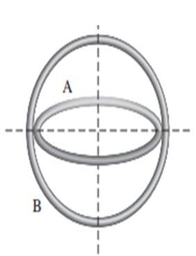
Figure P32.29
Expert Solution & Answer

Trending nowThis is a popular solution!

Students have asked these similar questions
A square, 44.0-turn coil that is 13.0 cm on a side with a
resistance of 0.900 2 is placed between the poles of a large
electromagnet. The electromagnet produces a constant,
uniform magnetic field of 0.400 T directed into the screen. As
suggested by the figure, the field drops sharply to zero at the
edges of the magnet. The coil moves to the right at a constant
velocity of 3.10 cm/s.
N-turn
coil
B into the screen
V
Q4: Show detailed work and pay attention to the units.
There are two different ways to calculate the potential difference across the bar, using the motional EMF expression or Faraday's Law. Show that both methods give
the same answer.
Use the right hand rule to figure out which end of the bar (A or B) will be at a higher potential due to the motion of the conductor in the field.
A doctor observes that when they apply a 2.0T B-field
perpendicular to the flow of blood in a blood vessel, their
multimeter displays a 40 mV voltage across the blood vessel.
The vessel itself is cylindrical in shape and has a radius of 1.5
cm.
a. Calculate how fast is the blood flowing through the
vessel?
b. What is the E-field induced across the walls of the vessel?
Chapter 32 Solutions
Physics for Scientists and Engineers: Foundations and Connections
Ch. 32.1 - To calculate the magnetic flux through the...Ch. 32.2 - Prob. 32.2CECh. 32.3 - Prob. 32.3CECh. 32.3 - Prob. 32.4CECh. 32.4 - Prob. 32.5CECh. 32.5 - Prob. 32.6CECh. 32.6 - Prob. 32.7CECh. 32.8 - Prob. 32.8CECh. 32.8 - Prob. 32.9CECh. 32 - A constant magnetic field of 0.275 T points...
Ch. 32 - Prob. 2PQCh. 32 - Prob. 3PQCh. 32 - Prob. 4PQCh. 32 - Prob. 5PQCh. 32 - Figure P32.6 shows three situations involving a...Ch. 32 - A rectangular loop of length L and width W is...Ch. 32 - The magnetic field through a square loop of wire...Ch. 32 - Prob. 9PQCh. 32 - Prob. 10PQCh. 32 - Suppose a uniform magnetic field is perpendicular...Ch. 32 - Prob. 12PQCh. 32 - A square conducting loop with side length a = 1.25...Ch. 32 - A The magnetic field in a region of space is given...Ch. 32 - A The magnetic field in a region of space is given...Ch. 32 - Prob. 16PQCh. 32 - Prob. 17PQCh. 32 - Prob. 18PQCh. 32 - A square loop with side length 5.00 cm is on a...Ch. 32 - A thin copper rod of length L rotates with...Ch. 32 - Figure P32.21 shows a circular conducting loop...Ch. 32 - Prob. 22PQCh. 32 - A square loop with side length L, mass M, and...Ch. 32 - Prob. 24PQCh. 32 - Prob. 25PQCh. 32 - Prob. 26PQCh. 32 - Prob. 27PQCh. 32 - A solenoid of area Asol produces a uniform...Ch. 32 - Two circular conductors are perpendicular to each...Ch. 32 - Two circular conducting loops labeled A and B are...Ch. 32 - Prob. 31PQCh. 32 - Prob. 32PQCh. 32 - Prob. 33PQCh. 32 - Prob. 34PQCh. 32 - Prob. 35PQCh. 32 - Find an expression for the current in the slide...Ch. 32 - The slide generator in Figure 32.14 (page 1020) is...Ch. 32 - Prob. 38PQCh. 32 - A thin conducting bar (60.0 cm long) aligned in...Ch. 32 - A stiff spring with a spring constant of 1200.0...Ch. 32 - A generator spinning at a rate of 1.20 103...Ch. 32 - Suppose you have a simple homemade AC generator...Ch. 32 - Prob. 43PQCh. 32 - Prob. 44PQCh. 32 - Prob. 45PQCh. 32 - Prob. 46PQCh. 32 - A square coil with a side length of 12.0 cm and 34...Ch. 32 - Prob. 48PQCh. 32 - Prob. 49PQCh. 32 - Prob. 50PQCh. 32 - Prob. 51PQCh. 32 - Prob. 52PQCh. 32 - Prob. 53PQCh. 32 - Prob. 54PQCh. 32 - Prob. 55PQCh. 32 - Prob. 56PQCh. 32 - Prob. 57PQCh. 32 - A step-down transformer has 65 turns in its...Ch. 32 - Prob. 59PQCh. 32 - Prob. 60PQCh. 32 - Prob. 61PQCh. 32 - Prob. 62PQCh. 32 - Prob. 63PQCh. 32 - A bar magnet is dropped through a loop of wire as...Ch. 32 - Prob. 65PQCh. 32 - Prob. 66PQCh. 32 - A circular coil with 75 turns and radius 12.0 cm...Ch. 32 - Each of the three situations in Figure P32.68...Ch. 32 - A square loop with sides 1.0 m in length is placed...Ch. 32 - Prob. 70PQCh. 32 - Two frictionless conducting rails separated by l =...Ch. 32 - Imagine a glorious day after youve finished...Ch. 32 - Prob. 73PQCh. 32 - A Figure P32.74 shows an N-turn rectangular coil...Ch. 32 - A rectangular conducting loop with dimensions w =...Ch. 32 - Prob. 76PQCh. 32 - A conducting rod is pulled with constant speed v...Ch. 32 - Prob. 78PQCh. 32 - A conducting single-turn circular loop with a...Ch. 32 - A metal rod of mass M and length L is pivoted...
Knowledge Booster


Learn more about
Need a deep-dive on the concept behind this application? Look no further. Learn more about this topic, physics and related others by exploring similar questions and additional content below.Similar questions
- A segment of wire 5.7 cm long is moving at a velocity of 2.89 m/s toward a parallel (much longer) wire which carries a current of 5.45 A. At a particular instant the wire segment is 5.7 cm away from the long, current-carrying wire. What is the induced emf (voltage) between the two ends of the wire segment? O 4.10E-06 V O 3.15E-06 V O 9.45E-07 V O 2.21E-06 Varrow_forwardA2.10 cm x 2.10 cm square loop of wire with resistance 1.00×10⁻² has one edge parallel to a long straight wire. The near edge of the loop is 1.10 cm from the wire. The current in the wire is increasing at the rate of 120 A/s.arrow_forwardTwo circular loops of wire surround an insulating rod as inFigure P20.53. Loop 1 carries a current I in the clockwise directionwhen viewed from the left end. If loop 1 moves towardloop 2, which remains stationary, what is the direction of theinduced current in loop 2 when viewed from the left end?arrow_forward
- 30. A short wire runs along an x axis from x = a to x = -a (Figure P30.30). At t = 0, there is a small sphere carry- ing charge +9o at x = a and a small sphere carrying charge -9o at x = -a. As the spheres discharge and a current is established in the wire, show that, for t>0, the generalized form of Ampère's law (Eq. 30.13) and the Biot-Savart law (Eq. 28.12) give the same result for the magnitude of the mag- netic field a distance b up the y axis. (Hint: Obtain the elec- tric flux through a circular disk in the yz plane, centered at the origin. Because the electric field is not constant over the surface of the disk, you must divide the disk into a nested set of rings of various radii and integrate. A representative ring should have radius r and radial extent dr.) •.. Figure P30.30 b -90arrow_forwardA conducting rod of length ℓ moves on two horizontal, frictionless rails as shown inFigure P31.26. If a constant force of 1.00 N moves the bar at 2.00 m/s through amagnetic field B that is directed into the page (a) what is the current through the 8.00-Ω resistor R? (b) What is the rate at which energy is delivered to the resistor? (c) Whatis the mechanical power delivered by the force Fapp?arrow_forward6. Rail guns have been suggested for launching projectiles into space without chemical rockets. A tabletop model rail gun (Figure A2.4) consists of two long, parallel, horizontal rails, l= 3.50 cm apart, bridged by a bar of mass m= 3.00 g that is free to slide without friction. The rails and bar have low electric resistance, and the current is limited to a constant I = 24.0 A by a power supply that is far to the left of the figure, so it has no magnetic effect on the bar. Figure A2.4 shows the bar at rest at the midpoint of the rails at the moment the current is established. We wish to find the speed with which the bar leaves the rails after being released from the midpoint of the rails. (a) Find the magnitude of the magnetic field at a distance of 1.75 cm from a single long wire carrying a current of 2.40 A. (b) For purposes of evaluating the magnetic field, model the rails as infinitely long. Using the result of part (a), find the magnitude and direction of the magnetic field at the…arrow_forward
- A resistor R is connected between two parallel conducting rails separated by 30 cm, as shown in the diagram. A conducting bar maintains electric contact with the rails as it moves relative to them with constant velocity from x = 20 cm to x = 48 cm in 0.6 seconds. A uniform 0.8 T field points into the page. Calculate the induced electric potential difference between the two ends of the bar.arrow_forwardThree loops of wire move near a long straight wire carrying a current as in Figure P20.9. What is the direction of the induced current, if any, in (a) loop A, (b) loop B, and (c) loop C. A B I C Figure P20.9arrow_forwardA P A circular conducting disc or radius g is rotating around its axis with an angular velocity w rad/s and is exposed to a magnetic field B = B, sin(wt) that is parallel to its axis in the out-of-page direction. If we connect a voltmeter between points A (the center of the rotating disc) and P (on the edge of the rotating disc), what will be the measured voltage Vap?arrow_forward
- 1. A 11.8 ?F capacitor is charged by a 25.0 V battery through a resistance R. The capacitor reaches a potential difference of 4.00 V at a time 3.00 s after charging begins. Find R. ________ kΩ 2.A proton moves perpendicular to a uniform magnetic field at a speed of 1.20 107 m/s and experiences an acceleration of 1.40 1013 m/s2 in the positive x-direction when its velocity is in the positive z-direction. Determine the magnitude and direction of the field. magnitude _______ PLEASE ANSWER BOTHarrow_forward7. A sheet of copper foil 1 mm thick, 5 cm wide and 1.75 m long is connected to a voltage source as shown. There is a magnetic field B = 2.5 T into the page. Assume copper has conductivity σ = 5.96 x 10⁷ mho/m and a charge carrier density n = 1028 electrons/m³. a) What is the current density J in the foil? b) What is the Hall voltage as measured by the voltmeter? c) Which point is at a higher potential, a or b? Voltmeter 20 Varrow_forwardYour physics professor is doing a demo to demonstrate Faraday’s law. He usesa 5m long wire of 10 Ohms total resistance, and he shapes it as a perfect square.Your professor places the loop in a plane perpendicular to a 2 Tesla uniformmagnetic field pointing from above into the plane of the loop. Then yourprofessor re-shaped the wire in five seconds from a square into a perfect circle.The new loop remains in the same plane.a. What is the magnitude of the average induced emf in the wire during thistime?b. Find the direction, and average magnitude of the current in the loopduring the deformation? Explain your reasoning.arrow_forward
arrow_back_ios
SEE MORE QUESTIONS
arrow_forward_ios
Recommended textbooks for you
 Physics for Scientists and Engineers: Foundations...PhysicsISBN:9781133939146Author:Katz, Debora M.Publisher:Cengage Learning
Physics for Scientists and Engineers: Foundations...
Physics
ISBN:9781133939146
Author:Katz, Debora M.
Publisher:Cengage Learning
What is Electromagnetic Induction? | Faraday's Laws and Lenz Law | iKen | iKen Edu | iKen App; Author: Iken Edu;https://www.youtube.com/watch?v=3HyORmBip-w;License: Standard YouTube License, CC-BY