
Videos
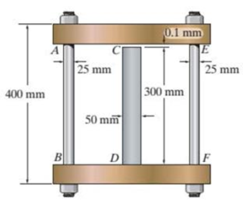
The assembly consists of two A992 steel bolts AB and EF and an 6061-T6 aluminum rod CD. When the temperature is at 30°C, the gap between the rod and rigid member AE is 0.1 mm. Determine the normal stress developed in the bolts and the rod if the temperature rises to 130°C. Assume BF is also rigid.
Prob. R9-1
Find the normal stress developed in the bolts and rod.
Answer to Problem 1RP
The normal stress developed in the bolts and rod are
Explanation of Solution
Given information:
The two bolts AB and EF are made of A992 steel.
The rod CD is made of 6061-T6 aluminum.
The Young’s modulus of the steel is
The Young’s modulus of the aluminum
The coefficient of thermal expansion of the steel
The coefficient of thermal expansion of the aluminum
The initial temperature
The finial temperature
The gap between the rod and rigid member AE is 0.1 mm.
The diameter of the bolts AB and EF
The diameter of the rod CD
The length of the bolts AB and EF
The length of the rod CD
Calculation:
Calculate the area of the bolts AB and EF
Substitute 25 mm for
Calculate the area of the rod CD
Substitute 50 mm for
Calculate the difference of temperature
Substitute
Show the free body diagram of the rigid cap as in Figure 1.
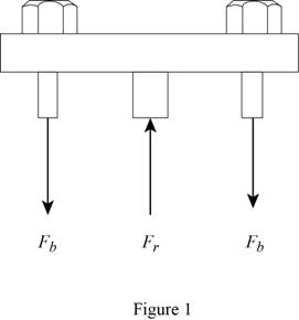
Calculate the vertical forces by applying the equation of equilibrium:
Sum of vertical forces is equal to 0.
Here,
Show the initial and final position of the assembly as in Figure 2.
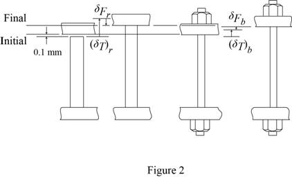
Here
The deformation is as follows:
Substitute
Calculate the force at the bolts AB and EF
Substitute
Calculate the force at the rod CD
Substitute 16,452 N for
Calculate the normal stress developed in the bolts AB and EF
Substitute 16,452 N for
Calculate the normal stress developed in the rod CD
Substitute 32,904 N for
Hence, the normal stress developed in the bolts and rod are
Want to see more full solutions like this?
Chapter 9 Solutions
Statics and Mechanics of Materials (5th Edition)


- The d = 13-mm-diameter solid rod passes through a D = 20-mm-diameter hole in the support plate. When a load Pis applied to the rod, the rod head rests on the support plate. The support plate has a thickness of b = 15 mm. The rod head has a diameter of a = 31 mm, and the head has a thickness of t= 10 mm. If the normal stress produced in the rod by load Pis 150 MPa, determine (a) the bearing stress acting between the support plate and the rod head. (b) the average shear stress produced in the rod head. (c) the punching shear stress produced in the support plate by the rod head. Support Plate - Hole diameter D P Rod Нead a Calculate the cross-sectional area of the rod. Answer: Arod = i mm2arrow_forwardThe 50-mm-diameter cylinder is made from Am 1004-T61 magnesium and is placed in the clamp when the temperature is T; = 15 °C. If the two 304-stainless-steel carriage bolts of the clamp each have a diameter of 10 mm, and they hold the cylinder snug with negligible force against the rigid jaws, determine the temperature at which the average normal stress in either the magnesium or the steel first becomes 12 MPa. 100 mm 150 mmarrow_forwardThe d = 13-mm-diameter solid rod passes through a D=21-mm-diameter hole in the support plate. When a load P is applied to the rod, the rod head rests on the support plate. The support plate has a thickness of b = 12 mm. The rod head has a diameter of a = 28 mm, and the head has a thickness of t = 8 mm. If the normal stress produced in the rod by load P is 150 MPa, determine (a) the bearing stress acting between the support plate and the rod head. (b) the average shear stress produced in the rod head. (c) the punching shear stress produced in the support plate by the rod head. Support Plate Hole diameter D Rod Head b Calculate the cross-sectional area of the rod. Answer: Arod mm²arrow_forward
- Determine the maximum force P and the corre- sponding maximum total strain energy that can be stored in the truss without causing any of the members to have permanent deformation. Each member of the truss has a OW diameter of 50 mm and is made of A-36 steel. E-N 1.2 m A B -0.9 m -0.9 m- VParrow_forwardThe 304 stainless steel post A has a diameter of d [d] mm F KN and is surrounded by a red brass C83400 tube B. Both rest on the rigid surface. If a force of F kN is applied to the rigid cap, determine the average nomal stress developed LImm To mm in the post and the tube. G,= 193 GPa, G= 101 GPa. mm = 200 mm F: 25N t =12 d=50 ro=75arrow_forwardThe d = 15-mm-diameter solid rod passes through a D = 20-mm-diameter hole in the support plate. When a load P is applied to the rod, the rod head rests on the support plate. The support plate has a thickness of b = 15 mm. The rod head has a diameter of a = 30 mm, and the head has a thickness of t = 9 mm. If the normal stress produced in the rod by load P is 200 MPa, determine (a) the bearing stress acting between the support plate and the rod head. (b) the average shear stress produced in the rod head. (c) the punching shear stress produced in the support plate by the rod head. Support Plate Hole diameter D Rod Head Calculate the cross-sectional area of the rod. Answer: Arodi mm²arrow_forward
- 4-69. The assembly has the diameters and material make- up indicated. If it fits securely between its fixed supports when the temperature is T = 20°C, determine the average normal stress in each material when the temperature reaches T2= 40°C. 304 Stainless steel 2014-T6 Aluminum C 86100 Bronze A 300 mm 200 mm D. Cj100 'mm -1.2 m- 2 marrow_forwardrod AB and The C83400-red-brass rod BC are 2014-T6-aluminum joined at the collar B and fixed connected at their ends. If there is no load in the members when T₁ = 10°C, determine the average normal stress in each member when T₂ = 50°C. Also, how far will the collar be displaced? The cross-sectional area of each member is 1130 mm². 1 m- B TT -0.6 m-arrow_forwardWhen the temperature is 10°C, the two rods are separated by a 0.5-mm 0.5 mm gap as shown. If the temperature rises to 90°C, determine (a) the normal stress in each rod, 300 mm 250 mm (b) the change in length of the stainless steel rod. A B Aluminum A = 2000 mm? E = 75 GPa a = 23 x 10-6/°C Stainless steel A = 800 mm? E = 190 GPa a = 17.3 x 10-/°Carrow_forward
- The aluminum shell is fully bonded to the brass core and the assembly is unstressed at a temperature of 15°C. Considering only axial defor-mations, determine the stress in the aluminum when the temperature reaches 195°C.arrow_forwardF8-11. The material for the 50-mm-long specimen has the stress-strain diagram shown. If P - 150 kN is applied and then released, determine the permanent elongation of the specimen. a (MPa) 20 mm 500 450 e (mm/mm) 0.00225 0.03arrow_forwardThe d - 15-mm-diameter solid rod passes through a D=20-mm-diameter hole in the support plate. When a load P is applied to the rod, the rod head rests on the support plate. The support plate has a thickness of b- 13 mm. The rod head has a diameter of a = 30 mm, and the head has a thickness of t= 10 mm. The shear stress in the rod head cannot exceed 130 MPa, the punching shear stress in the support plate cannot exceed 90 MPa, and the bearing stress between the rod head and the support plate cannot exceed 140 MPa. Determine the maximum value of Pmax that can be supported by the structure. Support Plate Rod Answer: Pmax i -Hole diameter D Head kN امarrow_forward
 Elements Of ElectromagneticsMechanical EngineeringISBN:9780190698614Author:Sadiku, Matthew N. O.Publisher:Oxford University Press
 Mechanics of Materials (10th Edition)Mechanical EngineeringISBN:9780134319650Author:Russell C. HibbelerPublisher:PEARSON
 Thermodynamics: An Engineering ApproachMechanical EngineeringISBN:9781259822674Author:Yunus A. Cengel Dr., Michael A. BolesPublisher:McGraw-Hill Education
 Control Systems EngineeringMechanical EngineeringISBN:9781118170519Author:Norman S. NisePublisher:WILEY
 Mechanics of Materials (MindTap Course List)Mechanical EngineeringISBN:9781337093347Author:Barry J. Goodno, James M. GerePublisher:Cengage Learning
 Engineering Mechanics: StaticsMechanical EngineeringISBN:9781118807330Author:James L. Meriam, L. G. Kraige, J. N. BoltonPublisher:WILEY