
Concept explainers
Videos
Three loops, all made of the same type of wire, are placed near the ends of identical solenoids as shown. The solenoids are connected in series. Assume that the magnetic field near the end of each of the solenoids is uniform.
LOOP 2 consists of two turns of a single wire that is twice as long as the wire used to make loop 1. Loop 3 is made of a single wire that is half as long as the wire used to make loop 1.
Just after the switch has been closed, the current through the battery begins to increase. The following questions concern the period of time during which the current is increasing.
1. Let
2. Let R represent the resistance of loop 1. Find the resistance of each of the other loops in terms of R. Explain.
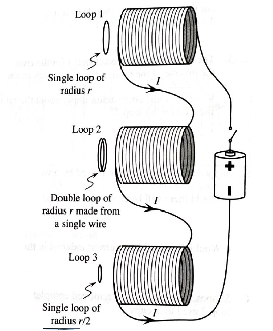
3. Find the current induced through the wire of each of the loops in terms of E and R.

Trending nowThis is a popular solution!

Learn your wayIncludes step-by-step video

Chapter 8 Solutions
Tutorials in Introductory Physics
Additional Science Textbook Solutions
Modern Physics
Conceptual Physics (12th Edition)
Applied Physics (11th Edition)
Life in the Universe (4th Edition)
University Physics with Modern Physics (14th Edition)
Physics for Scientists and Engineers with Modern Physics


- Solenoid A has length L and N turns, solenoid B has length 2L and N turns, and solenoid C has length L/2 and 2N turns. If each solenoid carries the same current, rank the magnitudes of the magnetic fields in the centers of the solenoids from largest to smallest.arrow_forwardA rectangular coil consists of N = 100 closely wrapped turns and has dimensions a = 0.400 m and b = 0.300 m. The coil is hinged along the y axis, and its plane makes an angle = 30.0 with the x axis (Fig. P22.25). (a) What is the magnitude of the torque exerted on the coil by a uniform magnetic field B = 0.800 T directed in the positive x direction when the current is I = 1.20 A in the direction shown? (b) What is the expected direction of rotation of the coil? Figure P22.25arrow_forwardA solenoid is 40 cm long, has a diameter of 3.0 cm, and is wound with 500 turns. If the current through the windings is 4.0 A, what is the magnetic field at a point on the axis of the solenoid that is (a) at the center of the solenoid, (b) 10.0 cm from one end of the solenoid, and (c) 5.0 cm from one end of the solenoid? (d) Compare these answers with the infinite-solenoid case.arrow_forward
- Why is the following situation impossible? A conducting rectangular loop of mass M = 0.100 kg, resistance R = 1.00 , and dimensions w = 50.0 cm by = 90.0 cm is held with its lower edge just above a region with a uniform magnetic field of magnitude B = 1.00 T as shown in Figure P30.34. The loop is released from rest. Just as the top edge of the loop reaches the region containing the field, the loop moves with a speed 4.00 m/s. Figure P30.34arrow_forwardA conducting rod of length = 35.0 cm is free to slide on two parallel conducting bars as shown in Figure P30.35. Two resistors R1 = 2.00 and R2 = 5.00 are connected across the ends of the bars to form a loop. A constant magnetic field B = 2.50 T is directed perpendicularly into the page. An external agent pulls the rod to the left with a constant speed of v = 8.00 m/s. Find (a) the currents in both resistors, (b) the total power delivered to the resistance of the circuit, and (c) the magnitude of the applied force that is needed to move the rod with this constant velocity. Figure P30.35arrow_forwardYou wish to move a rectangular loop of wire into a region of uniform magnetic field at a given speed so as to induce an emf in the loop. The plane of the loop must remain perpendicular to the magnetic field lines. In which orientation should you hold the loop while you move it into the region of magnetic field so as to generate the largest emf? (a) with the long dimension of the loop parallel to the velocity vector (b) with the short dimension of the loop parallel to the velocity vector (c) either way because the emf is the same regardless of orientationarrow_forward
- A piece of insulated wire is shaped into a figure eight as shown in Figure P23.12. For simplicity, model the two halves of the figure eight as circles. The radius of the upper circle is 5.00 cm and that of the lower circle is 9.00 cm. The wire has a uniform resistance per unit length of 3.00 Ω/m. A uniform magnetic field is applied perpendicular to the plane of the two circles, in the direction shown. The magnetic field is increasing at a constant rate of 2.00 T/s. Find (a) the magnitude and (b) the direction of the induced current in the wire. Figure P23.12arrow_forwardA circular loop of wire with a radius of 4.0 cm is in a uniform magnetic field of magnitude 0.060 T. The plane of the loop is perpendicular to the direction of the magnetic field. In a time interval of 0.50 s, the magnetic field changes to the opposite direction with a magnitude of 0.040 T. What is the magnitude of the average emf induced in the loop? (a) 0.20 V (b) 0.025 V (c) 5.0 mV (d) 1.0 mV (e) 0.20 mVarrow_forwardA metal rod of mass m slides without friction along two parallel horizontal rails, separated by a distance and connected by a resistor R, as shown in Figure P30.13. A uniform vertical magnetic field of magnitude B is applied perpendicular to the plane of the paper. The applied force shown in the figure acts only for a moment, to give the rod a speed v. In terms of m, , R, B, and v, find the distance the rod will then slide as it coasts to a stop. Figure P30.13arrow_forward
- A wire is bent in the form of a square loop with sides of length L (Fig. P30.24). If a steady current I flows in the loop, determine the magnitude of the magnetic field at point P in the center of the square. FIGURE P30.24arrow_forwardTwo frictionless conducting rails separated by l = 55.0 cm are connected through a 2.00- resistor, and the circuit is completed by a bar that is free to slide on the rails (Fig. P32.71). A uniform magnetic field of 5.00 T directed out of the page permeates the region, a. What is the magnitude of the force Fp that must be applied so that the bar moves with a constant speed of 1.25 m/s to the right? b. What is the rate at which energy is dissipated through the 2.00- resistor in the circuit?arrow_forward
 Principles of Physics: A Calculus-Based TextPhysicsISBN:9781133104261Author:Raymond A. Serway, John W. JewettPublisher:Cengage Learning
 Physics for Scientists and Engineers: Foundations...PhysicsISBN:9781133939146Author:Katz, Debora M.Publisher:Cengage Learning
 Physics for Scientists and Engineers with Modern ...PhysicsISBN:9781337553292Author:Raymond A. Serway, John W. JewettPublisher:Cengage Learning
 Physics for Scientists and EngineersPhysicsISBN:9781337553278Author:Raymond A. Serway, John W. JewettPublisher:Cengage Learning
 Physics for Scientists and Engineers, Technology ...PhysicsISBN:9781305116399Author:Raymond A. Serway, John W. JewettPublisher:Cengage Learning