
Concept explainers
(a)
To sketch:The safe operating area for the transistor and the load line on the same graph.
(a)
Answer to Problem 8.5P
Thearea for the safe operation of the transistor and the load line for the transistor is shown in Figure 1.
Explanation of Solution
Calculation:
The sketch for the safe operating area of the transistor is shown below.
The required diagram is shown in Figure 1
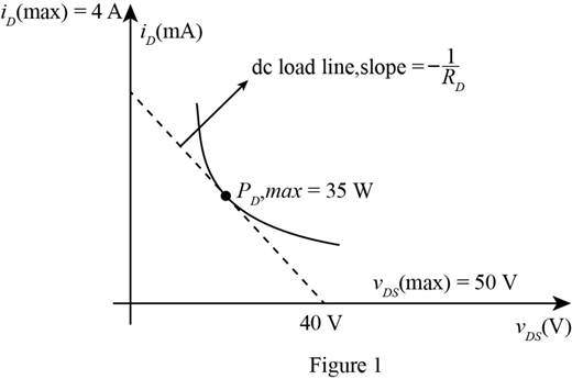
The above figure shows the safe region under which the transistor must be operated. The graph is plotted under the linear current and voltage scale. The sketch for the load line is dotted and is given by
Conclusion:
Therefore, the area for the safe operation of the transistor and the load line for the transistor is shown in Figure 1
(b)
The value of the drain current.
(b)
Answer to Problem 8.5P
Thepower at
Explanation of Solution
Calculation:
The expression for the voltage
The expression for the drain current is given by,
Substitute
The expression for the drain to source voltage is given by,
Substitute
The expression for the power dissipation is given by,
Substitute
Substitute
Substitute
Substitute
Substitute
Substitute
Substitute
The expression for the drain current in the non saturated region is given by,
Substitute
The expression for the drain current by ohm’s law is given by,
Substitute
Substitute
Substitute
Substitute
Substitute
Substitute
Substitute
Substitute
Conclusion:
Therefore, the power at
(c)
Whether there is a possibility of transistor getting damage.
(c)
Answer to Problem 8.5P
Yes, thetransistor will get damaged at
Explanation of Solution
The power of the transistor at
The above power is greater than the rated power of the transistor this means that the transistor gets damaged at
Want to see more full solutions like this?
Chapter 8 Solutions
Microelectronics: Circuit Analysis and Design


- For the given BJT circuit, determine the operating point and plot the DC load line showing the Ic(sat) and Vce(max). 16 V 510 k2 Ing Ico 1.8kQ2 VC Vcto B-120arrow_forwardSet up a midpoint bias for a JFET with IDSS = 14 mA and VGS(off) = -10 V. Use a 24 V dc source as the supply voltage. Show the circuit and resistor values. Indicate the value of ID. Indicate the value of VGS. Indicate the value of VDS.arrow_forwardQuestion 3: If the currents are in the same direction for a pair of parallel running wires, the currents on the wires are referred as Common Mode currents, ICM. On the other hand, if one of the currents is running in reverse direction (as they should normally do), the currents are referred as Differential Mode currents, IDM. It is essential in analog circuit design to keep track of differential and common mode currents. Referring to the following illustrations, assume that the separation between the wires, d, is 4 mm, the magnetic field observation point, S, is 20 mm away from the right wire, ICM- 5 mA, and IDM= 150 mA.arrow_forward
- 63. Which of the following conditions limit the analysis of quiscent point (Q-point)? A. The circuit should be at dynamic state B. The circuit requires no active condition C. The circuit should be subjected to both AC and DC environment D. The circuit is limited to actual operating environment E. None of the abovearrow_forwardBuild an AC/DC dual power supply circuit that draws a 60Vp-p sinusoidal voltage, to provide a dc output voltage of +15 V. Full analysis of voltages and currents should be included. What modifications would you recommend to draw more current while maintaining same output voltage?arrow_forwardFor the circuit shown below: Find the maximum and minimum Zener current.arrow_forward
- 3. Write down which transistor structure each curve characteristic belongs to in the figure. Ip -VGS -VGS +VGs (c) VGS (b) (a)arrow_forward8.* A single phase bridge rectifier supplies a IkW washing machine induction motor drive. The smoothing capacitance is 6.8 mF and the smoothing inductance is 5 mH. At full load, the equivalent resistance of the induction motor is 24 2. The ac supply is 220 V (60Hz). (a) (b) (c) Estimate the ripple What is the capacitor 'de link' voltage under full load? What is the % voltage regulation no load to full load? ?arrow_forward8.15 MECT361 Mechatronics Components and Instrumentation 8.15. Using the Internet, look up the specifications for the National Semiconductor ( www.national.com ) ADC0800 8-bit A/D converter. Determine the maximum sam- pling rate and the method for performing the conversion. Also define each of the inputs and outputs. PLEASE GIVE ME THE REFRENCE I Will get zero if you didn't put the refrencearrow_forward
- Part 1) Consider a step down converter with a resistive load. It is supplied by a DC power source of magnitude Vs = 160 V. The switching period is 0.25 ms and the duty cycle k is first set to 0.5. The load is resistive with R=10 Ohms. The critical value of L and the critical value of C are equal to: a. 0.625mH and 0.392uF b. 0.625mH and 0.196uF c. 0.312mH and 0.196uF d. None of these Part2) Now consider the same given but the load is an inductive load with R=10 Ohms and L=10 mH. The switch is ideal. Calculate The RMS load current Io and the RMS converter current Ir are equal to: Select one: a. 5A and 3.54A b. None of these c. 8A and 5.66A d. 12.5A and 8.84Aarrow_forwardExercise 2: Calculate the following i)Voltage across resistors R2, R5, R7. (Vrms) ii) Current flowing through the circuit. (Irms) iii) Calculate the peak to peak-peak voltage (Vpk-pk) and peak-peak current (I pk-pk) iv) Calculate the time period of the waveformarrow_forwardA buck-boost converter operates with an input battery. It converts +12 V to –12 V at apower level of about 75 W. the switching frequency is 120 kHz. The switches have200 ns switching time. The battery has an internal series resistance of 0.2 and seriesinductance of 200 nH. (a) What is the operating value of the duty ratio? What power is lost in the battery resistance? (b) Propose an interface structure to improve operation and decrease losses. What are the duty ratio and battery resistance loss with your interface in place?arrow_forward
 Introductory Circuit Analysis (13th Edition)Electrical EngineeringISBN:9780133923605Author:Robert L. BoylestadPublisher:PEARSON
 Delmar's Standard Textbook Of ElectricityElectrical EngineeringISBN:9781337900348Author:Stephen L. HermanPublisher:Cengage Learning
 Programmable Logic ControllersElectrical EngineeringISBN:9780073373843Author:Frank D. PetruzellaPublisher:McGraw-Hill Education
 Fundamentals of Electric CircuitsElectrical EngineeringISBN:9780078028229Author:Charles K Alexander, Matthew SadikuPublisher:McGraw-Hill Education
 Electric Circuits. (11th Edition)Electrical EngineeringISBN:9780134746968Author:James W. Nilsson, Susan RiedelPublisher:PEARSON
 Engineering ElectromagneticsElectrical EngineeringISBN:9780078028151Author:Hayt, William H. (william Hart), Jr, BUCK, John A.Publisher:Mcgraw-hill Education,