
Videos
The yielding factor of safety.
The load factor.
The joint separation factor.
Answer to Problem 40P
The yielding factor of safety is
The load factor is
The joint separation factor is
Explanation of Solution
Write the expression tensile load per bolt.
Here, tensile load per bolt is
Write the expression for cross section area of sealing.
Here, area is
Write the expression for grip.
Here, total thickness of plate and washer is
Write the expression for length of bolt.
Write the expression for threaded length.
Here threaded length is
Write the expression for area of unthreaded portion.
Here, the area of unthreaded portion is
Write the expression for length of unthreaded portion in grip.
Here, the length of unthreaded portion in grip is
Write the expression for length of threaded portion in grip
Here, length of threaded portion in grip is
Write the expression for bolt stiffness.
Here, bolt stiffness is
Write the expression for stiffness of top frusta.
Here, the stiffness of top frusta is
Write the expression for total spring rate of the member.
Here, the total spring rate of the member is
Write the expression for joint stiffness constant.
Here, joint stiffness constant is
Write the expression for preload.
Here, preload is
Write the expression for load factor
Here, load factor is
Write the expression for yielding factor of safety.
Here, yielding factor of safety is
Write the expression for load factor guarding against joint separation.
Here, load factor guarding against joint is
Write the expression for total external load.
Here, the total load is
Write the expression for load on the bolt.
Here, the load on the bolt is
Write the expression for cross section area of the cylinder.
Here, area of cylinder is
Conclusion:
Substitute
Substitute
Substitute
Substitute
Substitute
Substitute
Substitute
Substitute
Refer to table 8-1 “Diameter and areas of unified screw threads UNC and UNF”, obtain tensile stress area for nominal diameter of
Refer to table 8-9 “SAE specification for steel”, to obtain the minimum proof strength as
Substitute
Figure (1) shows the frustum of the cone for compressive load on the joint.
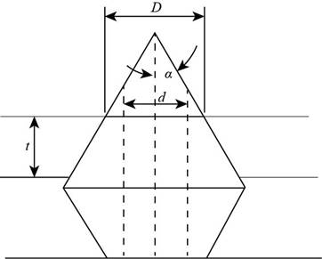
Figure-(1)
Write the expression for thickness of frusta.
Write the expression for diameter of the top frusta.
Substitute
Write the expression for thickness of middle frusta.
Write the expression for diameter of the middle frusta.
Substitute
Write the expression for thickness of lower frusta.
Write the expression for diameter of the lower frusta.
Substitute
Substitute
Substitute
Substitute
Substitute
Substitute
Substitute
Substitute
Thus the load factor is
Substitute
Thus the yielding factor of safety is
Substitute
Thus the load factor against joint separation is
Want to see more full solutions like this?
Chapter 8 Solutions
Shigley's Mechanical Engineering Design (McGraw-Hill Series in Mechanical Engineering)


- Two plates are clamped by a 3/4-10 UNC SAE Grade 5 bolt and regular nut with a 3/4-W plain washer as shown in figure. Top plate is made of grey cast iron and bottom plate is steel. An axial force of 12kN is acted upon the joint. Round off the length of the bolt to nearest 1/4in. Assume bolts are preloaded to 75% of proof load. 1. Determine the bolt stiffness kb. 2. Determine the member stiffness km. 3. Determine the yielding factor of safety of the bolt. 4. Determine the load factor for the bolt. 5. Determine the load factor guarding against joint separation. 1.25 in 1.00 inarrow_forwardThe figure gives the cross-section of a grade 25 cast-iron pressure vessel. A total of N bolts are to be used to resist a separating force of 150 kN. (a) Determine kb, km, and C. (b) Find the number of bolts required for a load factor of 2 where the bolts may be reused when the joint is taken apart. (c) With the number of bolts obtained in part (b), determine the realized load factor for overload, the yielding factor of safety, and the load factor for joint separation. Use (SI) units as it appliesarrow_forwardProblem 3: A Hexagonal bolt connects two members. The joint has a gap 1 = 2 in and the applied load is 2000 lb. Both of the clamped parts are steel. A preload of 90% the bolt's proof strength will be applied first. For this design, an SAE grade 1, 5/16"-18 UNC-2A bolt is chosen made from A307 with rolled threads. Washers are included between the head and the joint, and between the nut and the joint. Determine a suitable length for the bolt? Find its safety factor against yielding and against joint separation. Are these values acceptable?arrow_forward
- 1. For a bolted assembly with six bolts, the stiffness of each bolt is k, = 3 Mlbf/in and the stiffness of the members is km = 12 Mlbf/in per bolt. An external load of 80 kips is applied to the entire joint. Assume the load is equally distributed to all the bolts. It has been determined to use 1/2 in-13 UNC grade 8 bolts with rolled threads. Assume a torque co-efficient of K = 0.2. a. Determine the maximum bolt preload that can be applied without exceeding the proof strength of the bolts. b. Determine the minimum bolt preload that can be applied while avoiding joint separation. c. Determine the value of torque in units of Ibf-ft that should be specified for preloading the bolts if it is desired to preload to 75% of the proof load. d. Determine the yielding factor of safety for part c). (based on proof strength)arrow_forwardThe figure shows a connection that employs three SAE grade 4 bolts. The tensile shear load on the joint is 4000 lbf. The members are bars of AISI 1020 HR steel. Assume the bolt threads do not extend into the joint. Find the factor of safety for each possible mode of failure. (Refer example problem 8.6 on pg. 445). in ∞ in 100 in 1 in in Đ 1in -2 in in-20 UNC 5 5 in inarrow_forwardThe cantilever bracket is bolted to a column with three M12x1.75 ISO 5.8 bolts. The bracket is made from AISI 1020 hot-rolled steel. Find the factors of safety for the following failure modes: shear of bolts, bearing of bolts, bearing of bracket, and bending of bracket. Lazima 36 36 Holes for M12x 1.75 bolts 8 mm thick 200- 12 ANarrow_forward
- Example 8-4 in SI Units. • Q-2 Figure gives the cross section of a grade 25 cast-iron pressure vessel. A total of N bolts are to be used to resist a M16 x 2 x 60 mm class 5.8 separating force of 36 kip (160.2 kN). • (a) Determine k,, Kmy and C. • (b) Find the number of bolts required for a load factor of 2 where the bolts may be reused when the joint is taken apart. hexagonal head bolt No: 25 CI 20 mm 20 mm • (c) With the number of bolts obtained in part (b), determine the realized load factor for overload, the yielding factor of safety, and the load factor for joint separation. H = 14.8 mmarrow_forward2- In the shown connection, the coefficient of friction is 0.05. Calculate the minimum allowable tightening torque to carry the load F=1000N. If high tensile bolt 9.8, calculate the design factor of safety. 30 mm 16 mm 16 mm 6 mm bolt M10x1.5 16 mm 16 mm + 6 mm Farrow_forwardCalculate the maximum tensile stress developed in a 1/4-20 bolt (Major dia = 0.2500" and Root dia = 0.1959"), 3" long, and a head height of 0.1875", if it is subjected to a load of 426 lbs.arrow_forward
- Calculate the dimensions of the I-section of a connecting rod, stating any assumptions. using the data below: Maximum cylinder pressure = 3.15N/mm² Cylinder bore = 100mm Factor of Safety=6 Crank length 95mm Connecting rod length=380mm Take the constant a=7500.arrow_forwardThe cantilever bracket Is bolted to a column with three M12 x 1.75 ISO 5.8 bolts. The bracket Is made from AISI 1020 hot- rolled steel. Assume the bolt threads do not extend into the Joint. Find the factors of safety for the following fallure modes: shear of bolts, bearing of bolts, bearing of bracket, and bending of the bracket. GIVE the overall jolnt factor of safety. Given: F= 2 KN. NOTE: This is a multi-part questlon. Once an answer Is submitted, you will be unable to return to this part. Holes for M12 x 1.75 bolts 8 mm thick 36 32 36 - 200- Column Find the factor of safety with respect to the shear stress In the bolts. The factor of safety with respect to the shear stress In the bolts ng Is 4.4arrow_forwardFor the lap connection shown, the rivets are 19-mm diameter and the plates are 8 mm thick. The rivets used are A502, Grade 1 and the plates are ASTM A36 with Fu = 400 MPa. Determine the value of Pin all possible modes of failure and the safe value of P that the connection can resist. Fv = 120 MPa, Fp = 1.2 Fu. Add 1.6 mm for the hole diameter. Ans. 297.6 KNarrow_forward
 Elements Of ElectromagneticsMechanical EngineeringISBN:9780190698614Author:Sadiku, Matthew N. O.Publisher:Oxford University Press
 Mechanics of Materials (10th Edition)Mechanical EngineeringISBN:9780134319650Author:Russell C. HibbelerPublisher:PEARSON
 Thermodynamics: An Engineering ApproachMechanical EngineeringISBN:9781259822674Author:Yunus A. Cengel Dr., Michael A. BolesPublisher:McGraw-Hill Education
 Control Systems EngineeringMechanical EngineeringISBN:9781118170519Author:Norman S. NisePublisher:WILEY
 Mechanics of Materials (MindTap Course List)Mechanical EngineeringISBN:9781337093347Author:Barry J. Goodno, James M. GerePublisher:Cengage Learning
 Engineering Mechanics: StaticsMechanical EngineeringISBN:9781118807330Author:James L. Meriam, L. G. Kraige, J. N. BoltonPublisher:WILEY