
Concept explainers
Videos
(a)
The points where the shearing stress is maximum and the values of the stress.
(a)
Answer to Problem 80P
The shearing stress is maximum at the points of
The maximum shear stress along the vertical leg is
The maximum shear stress along the horizontal leg is
The maximum shear stress at the corner of the leg is
Explanation of Solution
Calculation:
Refer to sample problem 6.6 in the text book.
Combined stress along the vertical leg
Combined stress along the horizontal leg
Modify Equation (1).
Calculate the point along the vertical leg differentiate both sides of the equation with respect to y as shown below.
Consider the condition
Hence, the shearing stress is maximum at the points of
Calculate the maximum shear stress along the vertical leg as shown below.
Substitute
Hence, the maximum shear stress along the vertical leg is
Modify Equation (2).
Calculate the point along the horizontal leg differentiate both sides of the equation with respect to z as shown below.
Consider the condition
Hence, the shearing stress is maximum at the points of
Calculate the maximum shear stress along the horizontal leg as shown below.
Substitute
Hence, the maximum shear stress along the horizontal leg is
The corner points of the horizontal and vertical legs are
Calculate the maximum shear stress at the corner point as shown below.
Substitute 0 for y in Equation (1).
Substitute 0 for z in Equation (2).
Therefore, the maximum shear stress at the corner of the leg is
(b)
Show that the points are located on the neutral axis for the loading P.
(b)
Answer to Problem 80P
The points y and z are located on the neutral axis for the loading P.
Explanation of Solution
Calculation:
Sketch the cross section along the neutral axis as shown below.
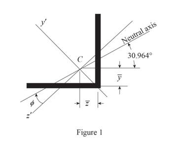
Refer to Figure 1.
Calculate the moment of inertia as shown below.
Along
Along
Consider the angle
Calculate angle
Substitute
Calculate the angle of the neutral axis from the horizontal as shown below.
Calculate the location of the centroid as shown below.
Along y axis:
Along z axis:
Calculate the neutral axis intersects for vertical leg as shown below.
Substitute
Calculate the neutral axis intersects for horizontal leg as shown below.
Substitute
Therefore, the points y and z are located on the neutral axis for the loading P
Want to see more full solutions like this?
Chapter 6 Solutions
Mechanics of Materials, 7th Edition


- 1.4 kN - m PROBLEM 8.43 A 10-kN force and a 1.4-kN - m couple are applied at the top of the 65-mm diameter brass post shown. Determine the principal stresses and maximum shearing stress at (a) point H, (b) point K. 10 kN 240 mm Omax = 30.0 MPa O min =-30.0 MPa Tmax = 30.0 MPa Omax = 7.02 MPa Omin =-96.0 MPa Tmay =51.5 MPaarrow_forwardI need the solution for this problem. Under normal operating conditions, the electric motor exerts a torque at point E of 12 kip-in. Knowing that each axis is solid, determine the maximum shear stress on (a) axis BC, (b) axis CD, (c) axis DE.arrow_forwardFor the loading shown, determine (a) the stress at points A and B, (b) the point where the neutral axis intersects line ABD.arrow_forward
- 5.86 The cast iron inverted T-section supports two concentrated loads of magni- tude P. The working stresses are 48 MPa in tension, 140 MPa in compression, and 30 MPa in shear. (a) Show that the neutral axis of the cross section is located at d = 48.75 mm and that the moment of inertia of the cross-sectional area about this axis is I = 11.918 x 106 mm“. (b) Find the maximum allowable value of P. 1.0 m 1.0 m 15 mm 3 m 150 mm NA- d 15 mm 150 mm FIG. P5.86arrow_forward5. V 6. Distinguish clearly between direct stress and bending stress.arrow_forwardThree forces are applied to the bar shown. Determine the normal and shearing stresses at (a) point a, (b) point b, (c) point c.arrow_forward
- 5.58 The vertical shear force acting on the cross section shown is 1800 lb. Determine the shear stress at (a) the neutral axis; and (b) 4 in. above the neutral axis.arrow_forwardTwo forces P can be applied separately or at the same time to a plate that is welded to a solid circular bar of radius r. Determine the largest compressive stress in the circular bar (a) when both forces are applied, (b) when only one of the forces is applied.arrow_forwardThe hydraulic cylinder CF, which partially controls the position of rod DE, has been locked in the position shown. Member BD is 5/8 in. thick and is connected to the vertical rod by a 3/8-in.-diameter bolt. Determine (a) the average shearing stress in the bolt, (b) the bearing stress at C in member BD. draw free-body diagramarrow_forward
- The tube shown has a uniform wall thickness of 12 mm. For the given loading, determine (a) the stress at points A and B, (b) the point where the neutral axis intersects line ABD.arrow_forwardIn the hanger shown the upper portion of link ABC is 9-mm thick and the lower portions are each 6-mm thick. Epoxy resin is used to bond the upper and lower portions together at B. The pin at A is of 9-mm diameter while a 6-mm-diameter pin is used at C. Determine (a) the shearing stress in pin A. (b) the shearing stress in pin C, (c) the largest normal stress in link ABC, (d) the average shearing stress on the bonded surfaces at B, (e) the bearing stress in the link at C. 30 mm 150 mm 40 mm 170 mm 240 mm 2400 N 120 marrow_forwardA centric load P is applied to the granite block shown. Knowing that the resulting maximum value of the shearing stress in the block is 2.5 ksi, determine (a) the magnitude of P, (b) the orientation of the surface on which the maximum shearing stress occurs, (c) the normal stress exerted on the surface, (d) the maximum value of the normal stress in the block.arrow_forward
 Elements Of ElectromagneticsMechanical EngineeringISBN:9780190698614Author:Sadiku, Matthew N. O.Publisher:Oxford University Press
 Mechanics of Materials (10th Edition)Mechanical EngineeringISBN:9780134319650Author:Russell C. HibbelerPublisher:PEARSON
 Thermodynamics: An Engineering ApproachMechanical EngineeringISBN:9781259822674Author:Yunus A. Cengel Dr., Michael A. BolesPublisher:McGraw-Hill Education
 Control Systems EngineeringMechanical EngineeringISBN:9781118170519Author:Norman S. NisePublisher:WILEY
 Mechanics of Materials (MindTap Course List)Mechanical EngineeringISBN:9781337093347Author:Barry J. Goodno, James M. GerePublisher:Cengage Learning
 Engineering Mechanics: StaticsMechanical EngineeringISBN:9781118807330Author:James L. Meriam, L. G. Kraige, J. N. BoltonPublisher:WILEY