
Videos
In the circuit shown in Figure P6.51, determine the range in small−signal voltage gain
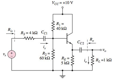
Figure P6.51
The range in small-signal voltage gain
Answer to Problem 6.51P
The final range of the voltage gain
The final range of the current gain
Explanation of Solution
Given:
Range of
The given circuit is:
From above circuit, considering BJT s single node, then by KCL, Quiescent emitter current
In CE mode,
Now, DC analysis of the given circuit:
Reduce source Vs to zero and open the capacitor as shown below:
The Theveninresistance is:
Modify the circuit as:
Therefore, Thevenin voltage from above circuit is
Modify the circuit as:
Applying KCL in the base-emitter loop to determine
From (3), (4) and (5) and
From equation (2) and
Now, small signal analysis of the given circuit:
Reduce dc voltage sources to zero, dc current source to open and capacitors to short.
Diffusion resistance
Input resistance and
The input resistance
Now, small signal current gain
From (3), (4) and (5) and
From equation (2) and
Diffusion resistance
Input resistance
The input resistance
Now, small signal current gain
The final range of the voltage gain
The final range of the current gain
Want to see more full solutions like this?
Chapter 6 Solutions
Microelectronics: Circuit Analysis and Design


- 1. is the decrease of voltage gain with frequency 2. the capacitance which effectively appears from input to output as the signal is applied is known asarrow_forwardHalle the equivalent inductance of the circuit of the figure 6.72. Suppose that all inducers are 10 mH.arrow_forwardExplain the relation between area, distance and capacitance RC Circuitsarrow_forward
- ASAParrow_forwardA resistor of 20 Ohms and a capacitance of unknown value when connected in in parallel across a 100V, 50Hz supply, take a current of 6A. The combination is now connected across a 100v supply of unknown frequency and the current falls to 5.5A. What is the frequency?arrow_forwardWhat will happen to the current in the PURE CAPACITOR if the frequency is adjusted higher? and What will happen to the current in the PURE CAPACITOR if the frequency is adjusted lower?arrow_forward
- An RC circuit has an emf of 5 V, a resistance of 10 ohms, a capacitance of 10 – 2 F, and initially a charge of 5 C on the capacitor. Determine the current flowing through the circuit. Ans.: I = - 99e – 10t/2arrow_forwardC5 What is the correct explanation for the voltage seen at Va in Figure C5? Va 1 Sost We will assume that the Vout Out Vb, capacitor is charged to a value determined by the feedback and the supply voltage +BVsat. Figure C5 A. The waveform on the capacitor looks like a discharge, and then a charging waveform to an equal but opposite magnitude voltage, B. The capacitor simply reverses its charge, with a charging waveform, C. The capacitor simply reverses its charge, with a discharging waveform, D. None of the above.arrow_forwardA series R–L–C circuit comprises a 5µF capacitor, a 4ohm resistor and a variable inductance L. The supply voltage is 10∠0◦ V at a frequency of 159.1 Hz. The inductance is adjusted until the p.d. across the 4 ohm resistanceis a maximum. Determine for this condition (a) the value of inductance, (b) the p.d. across each component and (c) the Q-factor of the circuit.arrow_forward
- A resistor of 20ohms and a capacitance of unknown value when connected in parallel across a 100V, 50Hz supply, takes a current of 6A. The combination is now connected across a 100V supply of unknown frequency and the current falls ro 5.5A. What is the frequency?arrow_forwardQ6: Find the values of resistance R and inductance L in the circuit of Figure R L 40 u.F 1=1.54-35° A 240 V, 50 Hzarrow_forwardWhat should be the limit of SWR? a. 0arrow_forward
 Introductory Circuit Analysis (13th Edition)Electrical EngineeringISBN:9780133923605Author:Robert L. BoylestadPublisher:PEARSON
 Delmar's Standard Textbook Of ElectricityElectrical EngineeringISBN:9781337900348Author:Stephen L. HermanPublisher:Cengage Learning
 Programmable Logic ControllersElectrical EngineeringISBN:9780073373843Author:Frank D. PetruzellaPublisher:McGraw-Hill Education
 Fundamentals of Electric CircuitsElectrical EngineeringISBN:9780078028229Author:Charles K Alexander, Matthew SadikuPublisher:McGraw-Hill Education
 Electric Circuits. (11th Edition)Electrical EngineeringISBN:9780134746968Author:James W. Nilsson, Susan RiedelPublisher:PEARSON
 Engineering ElectromagneticsElectrical EngineeringISBN:9780078028151Author:Hayt, William H. (william Hart), Jr, BUCK, John A.Publisher:Mcgraw-hill Education,