
Concept explainers
Videos
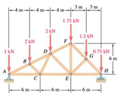
Using the method of joints, determine the force in each member of the double-pitch roof truss shown. State whether each member is in tension or compression.
The force in each of the member of the double-pitch roof truss using method of joints and whether each member is in tension or compression.
Answer to Problem 6.165RP
The force in member
Explanation of Solution
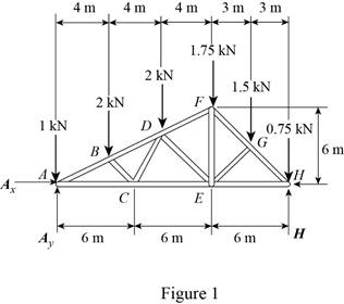
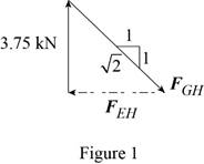
The free-body diagram of the truss is shown in figure 1.
The sum of the moments about the point
Here,
Write the equation for
Here,
Put the above equation in equation (I).
The
Here,
Write the expression for
Here,
Put the above equation in equation (II).
The
Here,
Write the expression for
Put the above equation in equation (III).
Here,
Substitute
The free-body diagram of joint A is shown in figure 2.
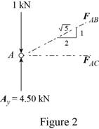
The joint A is subject to the forces exerted by
Obtain the magnitudes of the two forces from proportion.
Here,
The free-body diagram of the joint B is shown in figure 4.
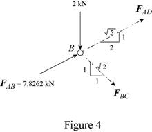
Write the equilibrium equations.
Here,
Write the expression for
Here,
Put the above equation in equation (IV).
The
Here,
Write the expression for
Put the above equation in equation (VI).
Multiply equation (V) by
Subtract equation (VII) from (V).
The free-body diagram of the joint C is shown in figure 5.
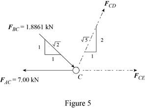
Write the expression for
Here,
Put the above equation in equation (VI).
Write the expression for
Here,
Put the above equation in equation (IV).
The free-body diagram of the joint D is shown in figure 6.
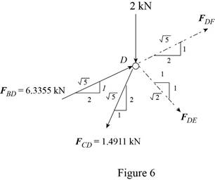
Write the expression for
Here,
Put the above equation in equation (IV).
Write the expression for
Put the above equation in equation (VI).
Add equations (VIII) and (IX).
Subtract equation (IX) from equation (VIII).
Consider the joint F. The free-body diagram of the joint F is shown in figure 7.
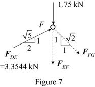
Write the expression for
Here,
Put the above equation in equation (IV).
Write the expression for
Here,
Put the above equation in equation (VI).
Consider the joint G. The free-body diagram of the joint G is shown in figure 8.
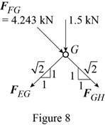
Write the expression for
Here,
Put the above equation in equation (IV).
Write the expression for
Put the above equation in equation (VI).
Add equations (X) and (XI).
Subtract equation (X) from equation (XI).
Consider the joint H. The free-body diagram of the joint H is shown in figure 9.
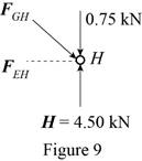
The joint H is subject to the forces exerted by
Obtain the magnitudes of the force from proportion.
Conclusion:
Thus, the force in member
Want to see more full solutions like this?
Chapter 6 Solutions
Vector Mechanics for Engineers: Statics and Dynamics


- The truss shown has a pin at A and a roller at C. Using the method of joints, determine the force in each member of the truss shown. State whether each member is in tension or compression. 6 ft 6 ft 19.9 kips D 8 ft-º 3 kips 17.5 ft-arrow_forwardUsing the method of joints, determine the force in each member of the truss shown. State whether each member is in tension or compression. You are required to tabulate the member forces in the table below.arrow_forwardUsing method of joints, determine the force in each member of the truss shown. Indicate whether the members are in tension or compression.arrow_forward
- Using the method of joints,determine the force in each member of the truss shown in given image. state whether each member is in tension or compression.arrow_forwardUsing the Method of Joints, determine the force in each member of the truss shown. State whether each member of the truss is in tension or compression. You do not need any "helper hints" for this problem as this problem is self-checking. 5 kip D 3 kip 6 ft 3 kip 5 kip -10 ft- -10 ftarrow_forwardPlease help me identify the zero force members in this truss.arrow_forward
- 3. Using the method of joints, determine the force in each member of the truss shown. State whether each member is in tension or compression. 2000 lb 1000 lb -12 ft - -12 ft- A B 8 ft D -12 ft 6 ft 6 ftarrow_forwardUsing the method of joints, determine the force in each member of the truss shown. State whether each member is in tension or compression.arrow_forwardDetermine the force acting in members BD, BE, CE and DE of the Bowstring truss shown below. Indicate whether tension or compression. Use the method of joints.arrow_forward
 Elements Of ElectromagneticsMechanical EngineeringISBN:9780190698614Author:Sadiku, Matthew N. O.Publisher:Oxford University Press
 Mechanics of Materials (10th Edition)Mechanical EngineeringISBN:9780134319650Author:Russell C. HibbelerPublisher:PEARSON
 Thermodynamics: An Engineering ApproachMechanical EngineeringISBN:9781259822674Author:Yunus A. Cengel Dr., Michael A. BolesPublisher:McGraw-Hill Education
 Control Systems EngineeringMechanical EngineeringISBN:9781118170519Author:Norman S. NisePublisher:WILEY
 Mechanics of Materials (MindTap Course List)Mechanical EngineeringISBN:9781337093347Author:Barry J. Goodno, James M. GerePublisher:Cengage Learning
 Engineering Mechanics: StaticsMechanical EngineeringISBN:9781118807330Author:James L. Meriam, L. G. Kraige, J. N. BoltonPublisher:WILEY