
Videos
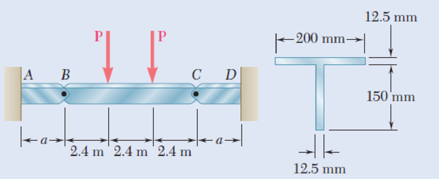
Beams AB, BC, and CD have the cross section shown and are pin-connected at B and C. Knowing that the allowable normal stress is +110 MPa in tension and –150 MPa in compression, determine (a) the largest permissible value of P if beam BC is not to be overstressed, (b) the corresponding maximum distance a for which the cantilever beams AB and CD are not overstressed.
Fig. P5.90
(a)
The largest permissible value of P for the condition that the beam BC is not overstressed.
Answer to Problem 90P
The largest permissible value of P is
Explanation of Solution
Given information:
The allowable normal stress of the material in tension is
The allowable normal stress of the material in compression is
Calculation:
Show the free-body diagram of the section BC as in Figure 1.
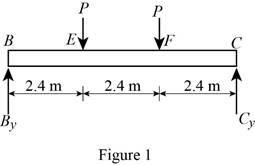
Determine the vertical reaction at point C by taking moment about point B.
Determine the vertical reaction at point B by resolving the vertical component of forces.
Show the free-body diagram of the section AB as in Figure 2.
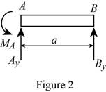
Determine the vertical reaction at point A by resolving the vertical component of forces.
Determine the moment at point A by taking moment about the point A.
Show the free-body diagram of the section CD as in Figure 3.
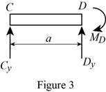
Determine the vertical reaction at point D by resolving the vertical component of forces.
Determine the moment at point D by taking moment about the point D.
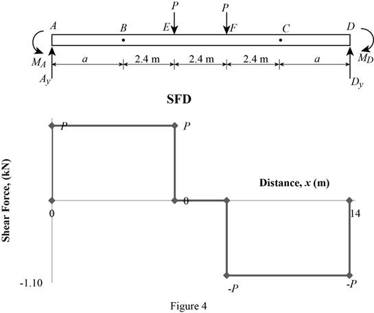
Shear force:
Show the calculation of shear force as follows;
Show the calculated shear force values as in Table 1.
| Location (x) m | Shear force (V) kN |
| A | P |
| E (Left) | P |
| E (Right) | 0 |
| F (Left) | 0 |
| F (Right) | –P |
| D | –P |
Plot the shear force diagram as in Figure 4.
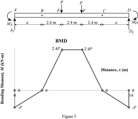
Bending moment:
Show the calculation of the bending moment as follows;
Show the calculated bending moment values as in Table 2.
| Location (x) m | Bending moment (M) kN-m |
| A | Pa |
| B | 0 |
| E | 2.4P |
| F | 2.4P |
| C | 0 |
| D | –Pa |
Plot the bending moment diagram as in Figure 5.
Show the free-body diagram of the T-section as in Figure 6.
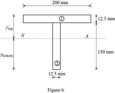
Determine the centroid in y-axis
Here, the area of the section 1 is
Refer to Figure 4;
Substitute
Determine the moment of inertia (I) using the equation.
Here, the depth of the section 1 is
Substitute 12.5 mm for
Refer to Figure 4;
Tension at Points B and D:
Refer to Figure 5;
Determine the moment at points B and D using the relation.
Substitute 110 MPa for
Compression at Points B and C:
Refer to Figure 5;
Determine the moment at points B and D using the relation.
Substitute –150 MPa for
Tension at maximum bending moment:
Refer to Figure 5;
Determine the maximum moment using the relation.
Substitute 110 MPa for
Compression at maximum bending moment:
Refer to Figure 5;
Determine the maximum moment using the relation.
Substitute –150 MPa for
Refer to the calculated distribution loads; the smallest value controls the design.
Refer to Figure 5;
Equate the maximum bending moment calculated and the maximum bending moment in the tension side.
Therefore, the largest permissible value of P for the condition that the beam BC is not overstressed is
(b)
The maximum distance a for the condition that the beams AB and CD are not overstressed.
Answer to Problem 90P
The maximum distance a for the condition that the beams AB and CD are not overstressed is
Explanation of Solution
Refer to Part (a), Figure 4;
The maximum bending moment in the beams AB and CD occurs at the ends A and D.
The calculated maximum bending moment at the points A and D is as follows:
The maximum allowable compression moment at the points A and D is as follows:
Equate the values;
Refer to the answer of the part (a);
Substitute 4.01 kN for P.
Therefore, the maximum distance a for the condition that the beams AB and CD are not overstressed is
Want to see more full solutions like this?
Chapter 5 Solutions
Mechanics of Materials, 7th Edition


- PROBLEM 4.The beam AB consisting of a cast iron plate of uniform thickness, b, and length, L, is to support the distributed load w(x) shown a) Knowing that the beam is to be of constant strength (fully stressed beam), express h in terms of x, L and ho. b) Determine the smallest value of ho if L=800 mm, b=25 mm, wo=300 kN/m and oall=200 MPa. w-=WoCos(ITX/2L) A ho Barrow_forwardHomework A timber beam AB of length L and rectangular cross section carries a single concentrated load P at its midpoint C. (a) Show that the ratio Tm/0, of the maximum values of the shearing and normal stresses in the beam is equal to h/2L, where h and L are, respectively, the depth and the length of the beam. (b) Determine the depth h and the width b of the beam, knowing that L = 2 m, P = 40 kN, 7,m = 960 kPa, and om 12 MPa. %3D L/2- - L/2 16|- Вarrow_forwardA steel bar and an aluminum bar are bonded together to form the composite beam shown. The modulus of elasticity for aluminum is 70 GPa and for steel is 200 GPa. Knowing that the beam is bent about a horizontal axis by a couple of moment M= 1500 N·m, determine the maximum stress in (a) the aluminum, (b) the steel.arrow_forward
- 250 mm PROBLEM 4.3 18 mm The wide-flange beam shown is made of a high-strength, low alloy steel for which o, = 450 MPa. Using a factor of safety of 3.0, determine the largest couple that can be applied to the beam when it is bent about C 360 mm M. + 10 mm the z axis. [Ans. 243.3 kNm] 18 mm Fig. P4.3 and P4.4 PROBLEM 4.4 Solve Prob, 4.3. assuming thatarrow_forwardA cable AB of span L and a simple beam A'B' of the same span are subjected to identical vertical loadings as shown. Show that the magnitude of the bending moment at a point C' in the beam is equal to the product T0h, where T0 is the magnitude of the horizontal component of the tension force in the cable and h is the vertical distance between point C and the chord joining the points of support A and B.arrow_forwardQI/Beams AB Problems, BC, and CD have the cross section shown and are pin-connected at B and C. Knowing that the allowable normal stress is +110 MPa in tension and -150 MPa in compression, (a) determine the largest permissible value of P (b) determine distance a. 12.5 mm -200 mm- 150 mm 24 m 2.4 m 2.4 m --l|- 12.5 mmarrow_forward
- A copper strip (E = 105 GPa) and an aluminum strip (E = 75 GPa) are bonded together to form the composite beam shown. Knowing that the beam is bent about a horizontal axis by a couple of moment M = 35 N.m, determine the maximum stress in (a) the aluminum strip, (b) the copper strip. Fig. P4.39 Aluminum Copper 24 mm 6 mm 6 mmarrow_forward(B) Q: The cantilever beam shown below has a circular cross section of 50mm outer diameter. Portion AB of the beam is hollow, with an inner diameter of 35mm. If the allowable bending stress is 140 MPa, determine (1) the largest allowable uniformly distributed load (w) that can be applied to the beam; (2) the bending stress at a point that is 7 mm below the top of the beam at section D. 50 mm W D B O! 35 mm A - 750 mm 250 mmarrow_forwardA 6-x 10-in. timber beam has been strengthened by bolting two - x 2-in. steel straps to it as shown below. The moduli of elasticity are 1.5 x 10⁶ psi for the wood and 30 x 106 psi for the steel. Knowing that the beam is bent about a horizontal axis by a bending moment of 200 kip in, determine (a) The maximum flexural stress in the wood. (b) The maximum flexural stress in the steel. 10 in. T 6 in.. wood 2 x 3/8 in. steelarrow_forward
- Five metal strips, each of 0.5 * 1.5-in. cross section, are bonded together to form the composite beam shown. The modulus of elasticity is 30* 106 psi for the steel, 15 *106 psi for the brass, 10 *106 psi for the aluminum. Knowing that the beam is bent about a horizontal axis by a couple of moment 12 kip·in., determine (a) the maximum stress in each of the three metals, (b) the radius of curvature of the composite beam.arrow_forwardA 1600-lb-in. couple is applied to a wooden beam, of rectangular cross section 1.5 by 3.5 in., in a plane forming an angle of 308 with the vertical (Fig. ). Determine (a) the maximum stress in the beam and (b) the angle that the neutral surface forms with the horizontal planearrow_forwardQI/Beams AB Problems, BC, and CD have the cross section shown and are pin-connected at B and C. Knowing that the allowable normal stress is +110 MPa in tension and -150 MPa in compression, (a) determine the largest permissible value of P (b) determine distance a. 12.5 mm - 200 mm- 150 mm 24 m 24 m 24 m 125 mmarrow_forward
 Elements Of ElectromagneticsMechanical EngineeringISBN:9780190698614Author:Sadiku, Matthew N. O.Publisher:Oxford University Press
 Mechanics of Materials (10th Edition)Mechanical EngineeringISBN:9780134319650Author:Russell C. HibbelerPublisher:PEARSON
 Thermodynamics: An Engineering ApproachMechanical EngineeringISBN:9781259822674Author:Yunus A. Cengel Dr., Michael A. BolesPublisher:McGraw-Hill Education
 Control Systems EngineeringMechanical EngineeringISBN:9781118170519Author:Norman S. NisePublisher:WILEY
 Mechanics of Materials (MindTap Course List)Mechanical EngineeringISBN:9781337093347Author:Barry J. Goodno, James M. GerePublisher:Cengage Learning
 Engineering Mechanics: StaticsMechanical EngineeringISBN:9781118807330Author:James L. Meriam, L. G. Kraige, J. N. BoltonPublisher:WILEY