
Mechanics of Materials (MindTap Course List)
9th Edition
ISBN: 9781337093347
Author: Barry J. Goodno, James M. Gere
Publisher: Cengage Learning
expand_more
expand_more
format_list_bulleted
Concept explainers
Videos
Textbook Question
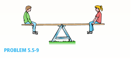
Chapter 5, Problem 5.5.9P
A seesaw weighing 3 lb/ft of length is occupied by two children, each weighing 90 lb (see figure). The center of gravity of each child is 8 ft from the fulcrum. The board is 19 ft long, 8 in. wide, and 1.5 in. thick.
What is the maximum bending stress in the board?
Expert Solution & Answer

Trending nowThis is a popular solution!

Students have asked these similar questions
For the problem shown below (left), W = 51 lbs while
L1 = 4.4 inches and L2 = 12 inches. This results in the
shear force diagram as shown on the right, where A, is
the reaction force in the vertical direction at point A.
Based on this shear diagram, what is the maximum
moment in the portion of the horizontal beam from x =
O to x = L1 in units of lb-in to two decimal places. (Be
sure to use a negative sign to designate a negative
moment if necessary.)
A
|--L1-——————— L2
Ay lb
0
-Ay lb
W
L1
L2
W
-L1-
BO
L1-
-X
The rectangular section used for the simply supported beam shown in Figure Q2 is 250 mm
deep and 320 mm wide. Determine the uniformly distributed load per metre that the beam may
carry over a distance of 6 m from the left end support if the bending stress is not to exceed 140
N/ mm.
w/m length
6 m
3 m
(a) The Figure la show the cross-section of a beam. All dimension are in cm.
10
2
10
Figure la
(i) Calculate the centroid of the cross-section measured from the bottom of the
cross section.
(ii) Calculate the moment of inertia, I, for this cross-section.
(iii)A pure bending moment of magnitude 1.0 kN.m is applied to the cross-
section, generating compression above the neutral axis, and tension below.
Calculate the maximum values of the tensile and compressive stress.
(iv)The bending moment is removed. The same beam cross-section is now subject
to a vertical shear force of 2.5 kN acting in the downward. Calculate the
maximum horizontal shear stress. Where does it occur?
Chapter 5 Solutions
Mechanics of Materials (MindTap Course List)
Ch. 5 - A steel wire with a diameter of d = 1/16 in. is...Ch. 5 - A copper wire having a diameter ofd = 4 mm is bent...Ch. 5 - A 4.75-in, outside diameter polyethylene pipe...Ch. 5 - A cantilever beam AB is loaded by a couple M0at...Ch. 5 - A thin strip of steel with a length of L =19 in....Ch. 5 - A bar of rectangular cross section is loaded and...Ch. 5 - A simply supported beam with a length L = 10 ft...Ch. 5 - A cantilever beam is subjected to a concentrated...Ch. 5 - A thin strip of hard copper (E = 16,000 ksi)...Ch. 5 - A steel wire (E = 200 GPa) of a diameter d = L25...
Ch. 5 - A thin, high-strength steel rule (E = 30 x 10ft...Ch. 5 - A simply supported wood beam AB with a span length...Ch. 5 - Beam ABC has simple supports at A and B and an...Ch. 5 - A simply supported beam is subjected to a in early...Ch. 5 - Each girder of the lift bridge (sec figure) is 180...Ch. 5 - A freight-car axle AS is loaded approximately as...Ch. 5 - A seesaw weighing 3 lb/ft of length is occupied by...Ch. 5 - During construction of a highway bridge, the main...Ch. 5 - The horizontal beam ABC of an oil-well pump has...Ch. 5 - A railroad tie (or sleeper) is subjected to two...Ch. 5 - A fiberglass pipe is lifted by a sling, as shown...Ch. 5 - A small dam of height h = 2.0 m is constructed of...Ch. 5 - Determine the maximum tensile stress (7, (due to...Ch. 5 - Determine the maximum bending stress emaxdue to...Ch. 5 - A simple beam A B of a span length L = 24 ft is...Ch. 5 - Determine the maximum tensile stress erand maximum...Ch. 5 - A cantilever beam A3, loaded by a uniform load and...Ch. 5 - A canti lever beam A B of a n isosceles t...Ch. 5 - A cantilever beam, a C12 x 30 section, is...Ch. 5 - A frame ABC travels horizontally with an...Ch. 5 - A beam ABC with an overhang from B to C supports a...Ch. 5 - A cantilever beam AB with a rectangular cross...Ch. 5 - A beam with a T-section is supported and loaded as...Ch. 5 - Consider the compound beam with segments AB and...Ch. 5 - A small dam of a height h = 6 ft is constructed of...Ch. 5 - A foot bridge on a hiking trail is constructed...Ch. 5 - A steel post (E=30×106) having thickness t = 1/8...Ch. 5 - Beam ABCDE has a moment release just right of...Ch. 5 - A simply supported wood beam having a span length...Ch. 5 - A simply supported beam (L = 4.5 m) must support...Ch. 5 - The cross section of a narrow-gage railway bridge...Ch. 5 - A fiberglass bracket A BCD with a solid circular...Ch. 5 - A cantilever beanie B is loaded by a uniform load...Ch. 5 - A simple beam of length L = 5 m carries a uniform...Ch. 5 - A simple beam AB is loaded as shown in the figure....Ch. 5 - A pontoon bridge (see figure) is constructed of...Ch. 5 - A floor system in a small building consists of...Ch. 5 - The wood joists supporting a plank Floor (see...Ch. 5 - A beam ABC with an overhang from B to C is...Ch. 5 - -12 A "trapeze bar" in a hospital room provides a...Ch. 5 - A two-axle carriage that is part of an over head...Ch. 5 - A cantilever beam AB with a circular cross section...Ch. 5 - A propped cantilever beam A BC (see figure) has a...Ch. 5 - A small balcony constructed of wood is supported...Ch. 5 - A beam having a cross section in the form of an un...Ch. 5 - A beam having a cross section in the form of a...Ch. 5 - Determine the ratios of the weights of four beams...Ch. 5 - Prob. 5.6.20PCh. 5 - A steel plate (called a cover ploie) having...Ch. 5 - A steel beam ABC is simply supported at A and...Ch. 5 - A retaining wall 6 ft high is constructed of...Ch. 5 - A retaining wall (Fig. a) is constructed using...Ch. 5 - A beam of square cross section (a = length of each...Ch. 5 - The cross section of a rectangular beam having a...Ch. 5 - A tapered cantilever beam A B of length L has...Ch. 5 - .2 A ligmio.irc ii supported by two vorlical beams...Ch. 5 - Prob. 5.7.3PCh. 5 - Prob. 5.7.4PCh. 5 - Prob. 5.7.5PCh. 5 - A cantilever beam AB with rectangular cross...Ch. 5 - A simple beam ABC having rectangular cross...Ch. 5 - A cantilever beam AB having rectangular cross...Ch. 5 - The shear stresses t in a rectangular beam arc...Ch. 5 - .2 Calculate the maximum shear stress tmaxand the...Ch. 5 - A simply supported wood beam is subjected to...Ch. 5 - A simply supported wood beam with overhang is...Ch. 5 - Two wood beams, each of rectangular cross section...Ch. 5 - A cantilever beam of length L = 2 m supports a...Ch. 5 - A steel beam of length L = 16 in. and...Ch. 5 - A beam of rectangular cross section (width/) and...Ch. 5 - A laminated wood beam on simple supports (figure...Ch. 5 - A laminated plastic beam of square cross section...Ch. 5 - A wood beam AB on simple supports with span length...Ch. 5 - A simply supported wood beam of rectangular cross...Ch. 5 - A square wood platform is 8 ft × 8 ft in area and...Ch. 5 - A wood beam ABC with simple supports at A and B...Ch. 5 - A wood pole with a solid circular cross section (d...Ch. 5 - A simple log bridge in a remote area consists of...Ch. 5 - A vertical pole consisting of a circular tube of...Ch. 5 - A circular pole is subjected to linearly varying...Ch. 5 - A sign for an automobile service station is...Ch. 5 - A steel pipe is subjected to a quadratic...Ch. 5 - -1 through 5.10-6 A wide-flange beam (see figure)...Ch. 5 - -1 through 5.10-6 A wide-flange beam (see figure)...Ch. 5 - -1 through 5.10-6 A wide-flange beam (see figure)...Ch. 5 - -1 through 5.10-6 A wide-flange beam (see figure)...Ch. 5 - -1 through 5.10-6 A wide-flange beam (see figure)...Ch. 5 - -1 through 5.10-6 A wide-flange beam (see figure)...Ch. 5 - A cantilever beam AB of length L = 6.5 ft supports...Ch. 5 - A bridge girder A B on a simple span of length L =...Ch. 5 - A simple beam with an overhang supports a uniform...Ch. 5 - A hollow steel box beam has the rectangular cross...Ch. 5 - A hollow aluminum box beam has the square cross...Ch. 5 - The T-beam shown in the figure has cross-sectional...Ch. 5 - Calculate the maximum shear stress tmax. in the...Ch. 5 - A prefabricated wood I-beam serving as a floor...Ch. 5 - A welded steel gird crhaving the erass section...Ch. 5 - A welded steel girder having the cross section...Ch. 5 - A wood box beam is constructed of two 260 mm × 50...Ch. 5 - A box beam is constructed of four wood boards as...Ch. 5 - Two wood box beams (beams A and B) have the same...Ch. 5 - A hollow wood beam with plywood webs has the...Ch. 5 - A beam of a T cross section is formed by nailing...Ch. 5 - The T-beam shown in the figure is fabricated by...Ch. 5 - A steel beam is built up from a W 410 × 85 wide...Ch. 5 - The three beams shown have approximately the same...Ch. 5 - Two W 310 × 74 Steel wide-flange beams are bolted...Ch. 5 - A pole is fixed at the base and is subjected to a...Ch. 5 - A solid circular pole is subjected to linearly...Ch. 5 - While drilling a hole with a brace and bit, you...Ch. 5 - An aluminum pole for a street light weighs 4600 N...Ch. 5 - A curved bar ABC having a circular axis (radius r...Ch. 5 - A rigid Trame ABC is formed by welding two steel...Ch. 5 - A palm tree weighing 1000 lb is inclined at an...Ch. 5 - A vertical pole of aluminum is fixed at the base...Ch. 5 - Because of foundation settlement, a circular tower...Ch. 5 - A steel bracket of solid circular cross section is...Ch. 5 - A cylindrical brick chimney of height H weighs w =...Ch. 5 - A flying but tress transmit s a load P = 25 kN,...Ch. 5 - A plain concrete wall (i.e., a wall with no steel...Ch. 5 - A circular post, a rectangular post, and a post of...Ch. 5 - Two cables, each carrying a tensile force P = 1200...Ch. 5 - Prob. 5.12.16PCh. 5 - A short column constructed of a W 12 × 35...Ch. 5 - A short column with a wide-flange shape is...Ch. 5 - A tension member constructed of an L inch angle...Ch. 5 - A short length of a C 200 × 17.1 channel is...Ch. 5 - The beams shown in the figure are subjected to...Ch. 5 - The beams shown in the figure are subjected to...Ch. 5 - A rectangular beam with semicircular notches, as...Ch. 5 - A rectangular beam with semicircular notches, as...Ch. 5 - A rectangular beam with notches and a hole (see...
Knowledge Booster


Learn more about
Need a deep-dive on the concept behind this application? Look no further. Learn more about this topic, mechanical-engineering and related others by exploring similar questions and additional content below.Similar questions
- The Straw Hat crew on their journey to Laugh Tale Island found a big treasure box (W). Luffy wanted to place the treasure box (W) as shown in the figure. A 100-mm x 300 mm rectangular beam is supported in a horizontal position. At point "A", it is being held by a pin and at "B" by a cable BD inclined 3 vertical to 4 horizontal. Assume all forces are applied to the beam along its central axis. Given that Fcparallel to grain = 10.50 MPa, W = 79 kN and E = 13800 MPa. Neglecting the weight of the beam and cable, determine whether the design is safe. Cable 2.4 m 2.4 marrow_forwardwe want to build a single-rail overhead crane in the workshop.when the load reaches the extreme point, it is 1800 mm away. the rail-shaped profile iron of the crane is connected from point B to point A by rope.the tensile stress of the rope is = 600 mpa. and the cross-sectional area is a=802 mm.according to other dimensions given (a=850mm b=1500 mm), this vince can hang No more than how many kg of load.(G=?)arrow_forwardThe three cross-sections shown in Figure A12 have the same cross-sectional area and are subjected to the same bending moment about their horizontal axis of symmetry. Section (a) is a square section. Sections (b) and (c) are composed of two rectangular sections that are placed loosely next to each other. If a, b and are their respective maximum bending stresses on the three sections, which one of the following relations is correct? 2a 2a 2a 2a a a (a) (b) а) басть сос b) σa=0b < oc α c) ба< Gb = ос d) a= b = 0c Figure A12 (c) To Po a aarrow_forward
- QUESTION 1: For the cantilever beam shown in below figure, draw the shearforce diagram and bending moment diagram and determine: 1.1 The magnitude of the sheaforce at 3 m from the free end. 1.2 The magnitude of the bending moment at the fixed end. 2 kN 1.5 kN/m 2 m 2 marrow_forward) A ship with a displacement tonnage of 5600 tons is floating without an inclination, as KG = 5.5m and GM = 0.5m. is known. A 33-ton load on the center line inside the ship can reach 10m pier and 3m up being moved. In this case, in order to keep the ship inclined, a tank on the port side is used as starboard. Ballast water is transferred to a tank on the side. Horizontal distance between the volume centers of the tanks 6 m What is the amount of ballast water that needs to be transferred?arrow_forward1. 2. 10 mm 10 mm 3. 5 mm 100 mm A beam section as shown in the sketch is subjected to a bendingmoment of Mx = 4 kN.m and a shear force of V = 2.5KN. 50 mm 100 mm Calculate the position of the centroid and the the second moment of area of the section about the sentroid horizontally. Draw the bending stress distribution through the height of the beam by calculating the bending stress at the critical positions Draw the shear stress distribution trough the height of the beam by calculating the shear stress below the flanges and at the centroid. 4. Draw the stress condition below the flanges, at the centroid and at the top and bottom of the beam.(7) 5. Draw the shearflow through the section. Show calculationsarrow_forward
- Situation 2 | Beam ABCDEFG below is subjected to multiple loads as show. The total length of the beam is 10m. Analyze the beam completely. 6 kN 10 kN 3 kN/m 2 kN 5 kN-m G 3000mm. 1000mm 1000mm. 2000mm. 1000mm 2000mm.arrow_forwardA simply supported beam, 50mm wide by 100mm high and 300 mm long is subjected to a concentrated load of 3000 N at a point 100 mm from one of the supports. Draw the shear force and bending moment diagrams for the beam.arrow_forwardDraw the shear and bending moment diagrams for the cantilevered beam below (figure not to scale). Identify the location and magnitude of max shear and bending stresses. 20 in 10 in 10 in 70 in 80 lbs 20 lbs 32.5 lbsarrow_forward
- QUESTION 4 There are 47 dowels - 10M, each measuring 910 mm, in a continuous concrete footing. What is the total rebar weight (kg)? (The mass of 1OM is 0.785 kg/m): QUESTION 5 The total length of a concrete beam (400mm X 600mm) is 10,427 mm. there are stirrups 10M@200mm on centre in this beam and the concrete cover is 25mm. How many stirrups does this concrete beam have?arrow_forwardThe beam shown in (Figure 1) weighs 320 lb/ft . Determine the magnitude of the internal normal force at point C. Determine the magnitude of the internal shear force at point C. Determine the magnitude of the internal moment at point C.arrow_forwardFor the given fig find the correct representation of the longitudinal variation of the bending stressarrow_forward
arrow_back_ios
SEE MORE QUESTIONS
arrow_forward_ios
Recommended textbooks for you
 Elements Of ElectromagneticsMechanical EngineeringISBN:9780190698614Author:Sadiku, Matthew N. O.Publisher:Oxford University Press
 Mechanics of Materials (10th Edition)Mechanical EngineeringISBN:9780134319650Author:Russell C. HibbelerPublisher:PEARSON
 Thermodynamics: An Engineering ApproachMechanical EngineeringISBN:9781259822674Author:Yunus A. Cengel Dr., Michael A. BolesPublisher:McGraw-Hill Education
 Control Systems EngineeringMechanical EngineeringISBN:9781118170519Author:Norman S. NisePublisher:WILEY
 Mechanics of Materials (MindTap Course List)Mechanical EngineeringISBN:9781337093347Author:Barry J. Goodno, James M. GerePublisher:Cengage Learning
 Engineering Mechanics: StaticsMechanical EngineeringISBN:9781118807330Author:James L. Meriam, L. G. Kraige, J. N. BoltonPublisher:WILEY
Elements Of Electromagnetics
Mechanical Engineering
ISBN:9780190698614
Author:Sadiku, Matthew N. O.
Publisher:Oxford University Press
Mechanics of Materials (10th Edition)
Mechanical Engineering
ISBN:9780134319650
Author:Russell C. Hibbeler
Publisher:PEARSON
Thermodynamics: An Engineering Approach
Mechanical Engineering
ISBN:9781259822674
Author:Yunus A. Cengel Dr., Michael A. Boles
Publisher:McGraw-Hill Education
Control Systems Engineering
Mechanical Engineering
ISBN:9781118170519
Author:Norman S. Nise
Publisher:WILEY
Mechanics of Materials (MindTap Course List)
Mechanical Engineering
ISBN:9781337093347
Author:Barry J. Goodno, James M. Gere
Publisher:Cengage Learning
Engineering Mechanics: Statics
Mechanical Engineering
ISBN:9781118807330
Author:James L. Meriam, L. G. Kraige, J. N. Bolton
Publisher:WILEY
Everything About COMBINED LOADING in 10 Minutes! Mechanics of Materials; Author: Less Boring Lectures;https://www.youtube.com/watch?v=N-PlI900hSg;License: Standard youtube license