
Concept explainers
Videos
A diffuser in a pipe flow is basically a slow expansion of the pipe diameter, which slows down the fluid velocity and increases the pressure (the Bernoulli effect). Water at room temperature flows with a volume flow rate of 00250 m3/s through a horizontal diffuser in which the pipe diameter increases gradually from D1= 6.00 to D2= 11.00 cm. The irreversible head loss through the diffuser is estimated to be 0.450 in. The flow is turbulent, and the kinetic energy correction factors at both the inlet and outlet of the diffuser are assumed to be 1.05.
(a) Calculate the pressure difference P2- P1in units of kPa using the energy equation.
(b) Repeat using the Bernoulli equation (ignore irreversible head losses and ignore kinetic energy correction factors-in other words, set the kinetic energy correction factors to 1). Calculate the percentage error in the result due to the Bernoulli approximation. and explain why (or why not) Bernoulli is applicable here.
(c) It may be surprising that the answer to part (a) is positive. i.e., the pressure rises downstream. How is this possible? Explain by calculating the change i n energy grade line EGL and the change in hydraulic grade line .HGL from the upstream to the downstream location. In particular, does EGL go up or down, and does HGL go up or down?
(a)
The pressure difference between outlet to inlet of diffuser.
Answer to Problem 116P
The pressure difference between outlet to inlet of diffuser is
Explanation of Solution
Given information:
The volume flow rate of diffuser is
Write the expression for area of pipe.
Here diameter of section is
Write the expression for velocity.
Here volume flow rate is
Consider inlet section as
Write the expression for energy equation in control volume.
Here, density is
Substitute
Calculation:
Substitute
Substitute
Substitute
Substitute
Refer to table "Properties of saturated water" to obtain density of water as
Substitute,
Conclusion:
The pressure difference between outlet to inlet of diffuser is
(b)
The pressure difference using Bernoulli equation.
The percent error due to Bernoulli approximation.
Answer to Problem 116P
The pressure difference using Bernoulli equation is
The percent error due to Bernoulli approximation is
Explanation of Solution
Given information:
Ignore irreversible head loss, kinetic energy correction factor
Write the expression for Bernoulli equation.
Write the expression for error percentage.
Here, pressure difference using energy equation is
Calculation:
Substitute
Substitute
Bernoulli equation is not applicable here because of pressure head loss and kinetic energy correction factor as greater
Conclusion:
The pressure difference using Bernoulli equation is
The percent error due to Bernoulli approximation is
(c)
The nature of Energy Grade line.
The nature of Hydraulic Grade line.
Answer to Problem 116P
The Energy Grade Line (EGL) decrease from the inlet to the exit and Energy grade Line goes down.
The Hydraulic Grade Line (HGL) increase from the inlet to the exit and Hydraulic grade Line goes up.
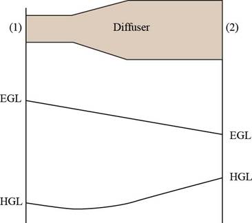
Figure-(1)
The Figure (1) shows the nature of Energy Grade Line (EGL) and Hydraulic Grade Line (HGL).
Explanation of Solution
Given information:
Write the expression for net Energy Grade Line (EGL).
Substitute
Write the expression for net Hydraulic Grade Line (HGL).
Substitute
Calculation:
Substitute
Substitute
Conclusion:
The Energy Grade Line (EGL) decrease from the inlet to the exit and Energy grade Line goes down.
The Hydraulic Grade Line (HGL) increase from the inlet to the exit and Hydraulic grade Line goes up.
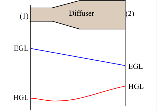
Figure (1)
The Figure (1) shows the nature of Energy Grade Line and Hydraulic Grade Line.
Want to see more full solutions like this?
Chapter 5 Solutions
Fluid Mechanics: Fundamentals and Applications


- A fireboat is to fight fires at coastal areas by drawing seawater with a density of 1030 kg/m^3 through a 10 cm diameter pipe at a rate of 0.04 m^3/s and discharging it through a hose nozzle with an exit diameter of 5 cm. The total irreversible head loss of the system is 3 m, and the position of the nozzle is 3 m above the sea level. For a pump efficiency of 70 percent, determine the water discharge velocity in m/s. a.25.7 b.39.2 c.56.3 d.20.4arrow_forwardAir enters a fan through a duct at a velocity of 6.3 m/s and an inlet static pressure of 2.5 cm of water less than atmospheric pressure. The air leaves the fan through a duct at a velocity of 11.25 m/s and a discharge static pressure of 7.62 cm of water above the atmospheric pressure. If the specific weight of the air is 1.2 kg/m3 and the fan delivers 9.45 m3/s, what is the fan efficiency when the power input is 13.75 kW at the coupling?arrow_forwardA Liquid fluid with a density of 1,750 kg/m3 from an elevated 2m open reservoir (P1=0 bars) flows before the pump at 7.5 m/s. The liquid fluid is pumped at an unknown final velocity to a 75 meter elevated tank with a pressure reading of 7.75 Bars. assuming Friction losses is 757.75J and the actual WORK of the pump is 1,933,400J. Calculate the Final Velocity in m/s if the pump's efficiency is just 75% and for every 1,000 kg of fluid per hour.arrow_forward
- In a water pipe, water flows at a constant rate of 22 L/s whose diameter is constant at 4 cm. The pressure drop across a valve in the pipe is measures to be 2 kPa, as shown below. Compute for the irreversible head loss of the valve, and the useful power needed to overcome the resulting pressure drop. Water 22 L/s AP = 2 kPaarrow_forwardIn a hydroelectric power plant, 100 m3/s of water flows from an elevation of 120 m to a turbine, where electric power is generated . The total irreversible head loss in the piping system from point 1 to point 2 (excluding the turbine unit) is determined to be 35 m. If the overall efficiency of the turbine–generator is 80 percent, estimate the electric power output.arrow_forwardd, = 3.0m B. A 3.0m diameter cylindrical tank is installed as a water tower which is used to supply water to a house. Exposed to environmental pressure, the level of the water inside the tank is 35m above the point of entry going through the house. The water flows through the intake pipe with diameter of 5.1 cm at a rate of 2.0x10-³ m³/s. The intake pipe is connected to a narrower pipe which has an inside diameter of 2.5 cm. h,= 35m a. Determine the speed of the water at point 2 b. Determine the static pressure at point 2 c. Determine the dynamic pressure at point 2 d. Determine the speed of the water at a height 5.0m above the level where the pipe enters the house e. Determine pressure of the water at point 3. 'dz - 1-27cm h2 = 5.0m d2=2.5cmarrow_forward
- A pump draws 20 kW of electrical power while pumping oil with a density of 780 kg/m^3 at a flow rate of 0.3 m^3/s. The diameters of the inlet and outlet pipes of the pump are 7 cm and 12 cm, respectively. Since the pressure increase in the pump is 220 kPa and the motor efficiency is 91%, determine the mechanical efficiency of the pump. (Ignore the kinetic energy correction factor, α=1, Ignore the height differences inside the pump, the head loss in the pump hL=0.5)arrow_forwardA fireboat is to fight fires at coastal areas by drawing seawater with a density of 1030 kg/m3 through a 10-cm-diameter pipe at a rate of 0.04 m3/s and discharging it through a hose nozzle with an exit diameter of 5 cm. The total irreversible head loss of the system is 3 m, and the position of the nozzle is 3 m above sea level. For a pump efficiency of 70 percent, determine the required shaft power input to the pump and the water discharge velocity.arrow_forwardYou want to know the power of a fan that is used to send air from a cooling system at 12 m linear distance by means of a 15 cm high stainless steel square pipe at a pressure of 105 Kpa and 25 ° C, to a ventilation port 25 m from the fan at 18 ° C at a pressure of 105 Kpa, with a flow of 0.25 m3/s (HP powerarrow_forward
- You have a 550 W pump with 70% efficiency available. Is it possible to use this pump to carry 10 m3/h of a liquid through a 4.7 cm inside diameter pipe, from one open tank to another, if the liquid is discharged at a point 10 m above the level of liquid in the suction tank and the total friction losses are 50 J/kg? The density and viscosity of the liquid are 1050 kg/m3 and 2 cp respectively.arrow_forward(b) A storage tank with base area 40 m2 is being filled with water through a duct in which the volumetric flow rate is 12 L/s, as shown in Fig. 3. Water is concurrently being extracted from the storage tank through two exit pipes with cross-section area 150 cm2. The inlet of the exit pipes is located at a certain height, denoted h in Fig. 3, above the bottom of the storage tank. Water is assumed to be inviscid and incompressible. exit pipes Ve 12 L/s k150 cm? K150 cm? 7 m storage tank (base area 40 m2) Figure 3 (i) Determine the flow speed V, in each exit pipe when a constant depth of 7 m is maintained in the storage tank. (ii) If the depth of water in the storage tank is initially 7 m and the flow speed in the exit pipes changes to V. = 2.4 m/s, it takes 1 hour for the water level to coincide with the inlet of the exit pipes. Determine the height h.arrow_forwardIn a pumping system handling water, the surface level of water in the open suction tank is 3m below the pump centerline, and the surface level in the open discharge tank is 22m above the pump centerline. The inlet piping is 7.62cm in diameter has an equivalent length of 26m of steel pipe. The discharge line is 6.35cm in diameter has an equivalent length of 72m. The pump discharge rate is 12.6 L/s. The friction factor to be 0.024 for both inlet and discharge pipes. Determine: a. the total head loss due to friction (HL = hfs + hfd) in meters 21.955 3.187 25.142 b. the total dynamic head in meters 50.142 45.955 49.142 c. the water power in kW 6.196 6.072 5.684arrow_forward
 Elements Of ElectromagneticsMechanical EngineeringISBN:9780190698614Author:Sadiku, Matthew N. O.Publisher:Oxford University Press
 Mechanics of Materials (10th Edition)Mechanical EngineeringISBN:9780134319650Author:Russell C. HibbelerPublisher:PEARSON
 Thermodynamics: An Engineering ApproachMechanical EngineeringISBN:9781259822674Author:Yunus A. Cengel Dr., Michael A. BolesPublisher:McGraw-Hill Education
 Control Systems EngineeringMechanical EngineeringISBN:9781118170519Author:Norman S. NisePublisher:WILEY
 Mechanics of Materials (MindTap Course List)Mechanical EngineeringISBN:9781337093347Author:Barry J. Goodno, James M. GerePublisher:Cengage Learning
 Engineering Mechanics: StaticsMechanical EngineeringISBN:9781118807330Author:James L. Meriam, L. G. Kraige, J. N. BoltonPublisher:WILEY