
Videos
(a)
Find the residual stress at
(a)
Answer to Problem 89P
The residual stress is
Explanation of Solution
Given information:
The yield stress for the beam is
The Young’s modulus of steel is
Calculation:
Show the cross-section of the beam as shown in Figure 1.
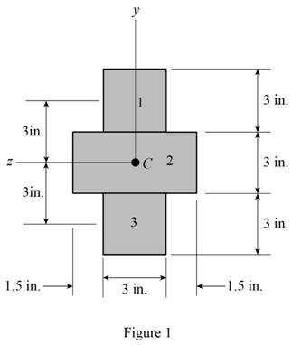
Refer Figure 1.
Refer to Figure 1.
Calculate the area of the cross section
Here, b is the width of the cross section and d is the depth of the cross section.
Calculate the area of the portion (1)
Substitute
Calculate the area of the portion (2)
Substitute
Calculate the moment of inertia
Calculate the moment of inertia of portion (1)
Substitute
Hence,
Calculate the moment of inertia of portion (2)
Substitute
Calculate the total moment of inertia
Substitute
Calculate the centroid (c) as shown below.
Substitute
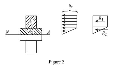
Sketch the stress acting on the cross-section of the beam as shown in Figure 2.
Refer Figure 1.
Calculate the area of the portion (2)
Substitute
Calculate the reaction applied to portion (1)
Substitute
Calculate the reaction applied to portion (2)
Substitute
Calculate the moment
Substitute
Calculate the stress
Substitute
Calculate the stress
Substitute
Calculate the residual stress at
Substitute
Calculate the residual stress at
Substitute
Sketch the stress distribution as shown in Figure 3.
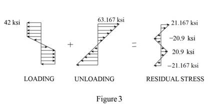
Hence, the residual stress is
(b)
Find the point where the residual stress is zero.
(b)
Answer to Problem 89P
The point where the residual stress is zero is
Explanation of Solution
Given information:
The yield stress for the beam is
The Young’s modulus of steel is
Calculation:
Consider that the residual stress
Calculate the yield stress
Calculate the point where the residual stress is zero as shown below.
Substitute
Substitute
Therefore, the point where the residual stress is zero is
(c)
Find the radius of curvature corresponding to the permanent deformation of the bar.
(c)
Answer to Problem 89P
The radius of curvature is
Explanation of Solution
Given information:
The yield stress for the beam is
The Young’s modulus of steel is
Calculation:
Refer to part (a).
The residual stress
Calculate the radius of curvature
Calculate the point where the residual stress is zero as shown below.
Substitute
Therefore, the radius of curvature is
Want to see more full solutions like this?
Chapter 4 Solutions
Mechanics of Materials, 7th Edition


- M = 500 Nm PROBLEM 4.2 В Knowing that the couple shown acts in the vertical plane, determine the stress at (a) point A, and (b) point B. [Ans. (a) -116.4 MPa (b) -87.3 MPa] 30 mm 40 mm Fig. P4.2arrow_forward20 40 20 Dimensions in mm PROBLEM 4.1 20 M = 15 kNm Knowing that the couple 80 shown acts in the vertical plane, determine the stress at (a) point A, and (b) point B. [Ans. (a) -61.2 MPa (b) 91.8 MPa] 20 В Fig. P4.1arrow_forwardProb.4: [2.37] The 1.5 m concrete post is reinforced with six steel bars, each with 28 mm diameter. Knowing the E, = 200 GPa and Ec = 200 GPa, determine the normal stresses in the steel and concrete when a 1550 kN axial centric force P is applied to the post. 450 mm 1.5 marrow_forward
- +3 in- B in. A vertical force P of magnitude 20 kips is applied at point C located on the axis of symmetry of the cross section of a short column. Knowing that y = 5 in., determine (a) the stress at point A, (b) the stress at point B, (c) the location of the neutral axis. 2 in. 4 in. A 2 in. 2 in. 1 in. (a) (b)arrow_forwardThe couple M is applied to a beam of the cross section shown in a plane forming an angle β with the vertical. Determine the stress at (a) point A, (b) point B, (c) point D.arrow_forwardA 1600-lb-in. couple is applied to a wooden beam, of rectangular cross section 1.5 by 3.5 in., in a plane forming an angle of 308 with the vertical (Fig. ). Determine (a) the maximum stress in the beam and (b) the angle that the neutral surface forms with the horizontal planearrow_forward
- 3 Knowing that for the extruded beam shown the allowable stress is 120 MPa in tension and 149 MPa in compression, determine the largest couple M that can be applied. 10 points 80 mm- 40 mm 54 mm The largest couple M that can be applied is 8.5824 KN-m.arrow_forward2.13 A steel plate, which is 1.5 m by 1.5 m and 30 mm thick, is lifted by four cables attached to its corners that meet at a point that is 2 m above the plate. Determine the required cross-sectional area of the cables if the stress in them is not to exceed 20 MPa. Steel plate Prob. 2.13 Cablesarrow_forwardPole AB is 12m. long and its weight W = 35kN. It is being lifted using BC and BD. When the pole is tilted at an angle of 60° from the x-axis, the resultant force acts at point A. 'p 2.6 m 3 m 4.5 m 3m 1. Find the tensile force (kN) in cable BC. В. 21.6 A. 22.5 C. 26.1 D. 28.2 2. Find the tensile force (kN) in cable BD. А. 13.1 В. 11.3 С. 14.5 D. 16.1 3. What is the value of the resultant (kN) acting at point A. В. 65.9 А. 69.5 C. 90.6 D. 56.9arrow_forward
- PROBLEM 1.3 3 in. 30 kips Two solid cylindrical rods AB and BC are welded together at B and loaded as shown. Determine the magnitude of the force P for which the tensile stress in rod AB is twice the magnitude of the compressive stress in rod BC. 30 kips 40 in PROBLEM 1.4 In Prob. 1.3, knowing that P = 40 kips, determine the average normal stress at the midsection of (a) rod AB, (b) rod BC.arrow_forward2. Given a front hand brake of a bicycle. The applied force, P = 70 N and the equivalent area and length of the cable is 1.02 mm² and 460 mm respectively. If the elongation of the cable is found to be 0.225 mm, find the normal stress in the cable. a. 137 b. 153 Brake cable, L = 460 mm 37.5 mm 50 mm Hand brake pivot A -100 mm- C. 168 d. 195 P (Resultant of distributed pressure) - Uniform hand brake pressurearrow_forward2.36 A 250-mm bar of 150 x 30-mm rectangular cross section consists of two aluminum layers, 5 mm thick, brazed to a center brass layer of the same thickness. If it is subjected to centric forces of magni- tude P = 30 kN, and knowing that E, = 70 GPa and E, = 105 GPa, determine the normal stress (a) in the aluminum layers, (b) in the brass layer. P' 250 mm 5 mm 5 mm 5 mm Aluminum Brass Aluminum P 30 mm Fig. P2.36arrow_forward
 Elements Of ElectromagneticsMechanical EngineeringISBN:9780190698614Author:Sadiku, Matthew N. O.Publisher:Oxford University Press
 Mechanics of Materials (10th Edition)Mechanical EngineeringISBN:9780134319650Author:Russell C. HibbelerPublisher:PEARSON
 Thermodynamics: An Engineering ApproachMechanical EngineeringISBN:9781259822674Author:Yunus A. Cengel Dr., Michael A. BolesPublisher:McGraw-Hill Education
 Control Systems EngineeringMechanical EngineeringISBN:9781118170519Author:Norman S. NisePublisher:WILEY
 Mechanics of Materials (MindTap Course List)Mechanical EngineeringISBN:9781337093347Author:Barry J. Goodno, James M. GerePublisher:Cengage Learning
 Engineering Mechanics: StaticsMechanical EngineeringISBN:9781118807330Author:James L. Meriam, L. G. Kraige, J. N. BoltonPublisher:WILEY