
Videos
For the frame and loading shown, determine the reactions at A E when (a) α = 30º, (b) α = 45 º.
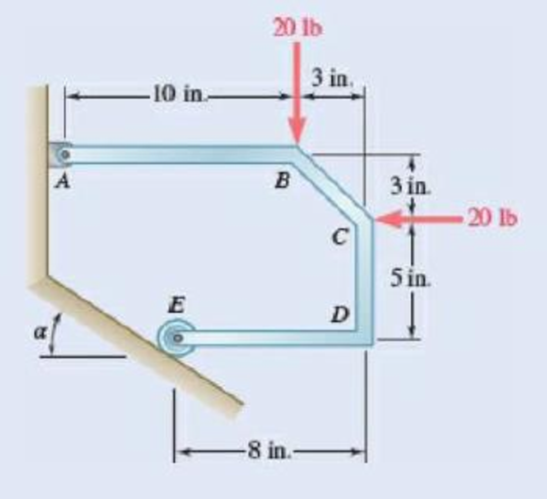
Fig. P4.27
(a)
The reaction at
Answer to Problem 4.27P
The reaction at
Explanation of Solution
Forces acting upward and rightward are considered as positive and the torque acting counter clockwise is considered as positive.
Let
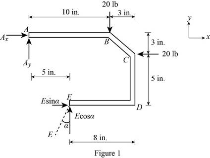
The free body diagram is sketched below as figure 1.
Here,
Write the expression for the moment at
Here,
Above equation implies that net moment at any point is the sum of product of each force acting on the system and perpendicular distance of the force about that point.
The moment at
The angle
The complete expression of moment
Here,
From figure 1, write the expression for the
From figure 1, write the expression for the
At equilibrium, the sum of the moment acting at
Write the expression for the total moment acting at
The forces along the
Therefore, write the expression for the net force along the
Here,
At equilibrium, the net force along the
The forces along the
Therefore, write the expression for the net force along the
Here,
At equilibrium, the net force along the
Write the expression for the magnitude of net reaction at
Here,
Let
Therefore, write the expression for the
Calculation:
Substitute
Substitute
Substitute
The negative sign indicates that direction of
Substitute
Substitute
The negative sign indicates that
Therefore, the reaction at
(b)
The reaction at
Answer to Problem 4.27P
The reaction at
Explanation of Solution
Take all vectors along the
Let
The free body diagram is sketched in figure 1.
Write the expression for the moment at
Here,
Above equation implies that net moment at any point is the sum of product of each force acting on the system and perpendicular distance of the force and the point.
The moment at
The angle
Thus, the complete expression of net anticlockwise moment
Here,
From figure 1, write the expression for the
From figure 1, write the expression for the
At equilibrium, the sum of the moment acting at
Write the expression for the total moment acting at
The forces along the
Therefore, write the expression for the net force along the
Here,
At equilibrium, the net force along the
The forces along the
Therefore, write the expression for the net force along the
Here,
At equilibrium, the net force along the
Write the expression for the magnitude of net reaction at
Here,
Let
Therefore, write the expression for the
Calculation:
Substitute
Substitute
Substitute
The negative sign indicates that direction of
Substitute
Therefore, the reaction at
Want to see more full solutions like this?
Chapter 4 Solutions
Vector Mechanics for Engineers: Statics and Dynamics


- 4.63 Horizontal and vertical links are hinged to a wheel, and forces are applied to the links as shown. Knowing that a = value of P and the reaction at A. 100 mm 100 mm 75 mm, determine the a В 100 mm 90 N Fig. P4.63 and P4.64arrow_forwardDetermine the reactions at A and C when (a) a= 0, (b) a = 0, (c) a = 30°.arrow_forwardRod ABC is bent in the shape of an arc of circle of radius R . Knowing that 0= 60°, determine the reaction (a) at B, (b) at C.arrow_forward
- Determine the reactions at A and B when (a) α=0, (b) α=90°,(c) α=30°.arrow_forwardSolve Prob. 4.106 for a = 1.5 m.(Reference to problem 4.106):The 6-m pole ABC is acted upon by a 455-N force as shown. The pole is held by a ball-and-socket joint at A and by two cables BD and BE. For a = 3 m, determine the tension in each cable and the reaction at A.arrow_forwardVector Mechanics for Engineers (EIT Review) Problem 4.34 Neglecting friction and the radius of the pulley, determine (a) the tension in cable ADB, (b) the reaction at C. A 8 in. Fig. P4.34 30 lb 8 in. B 20 in.- D 15 in.arrow_forward
- Three rods are welded together to form a "corner" that is supported by three eyebolts. Neglecting friction, determine the reactions at A, B, and C when P= 240 lb, a = 12 in., b= 8 in., and c= 10 in. Solve Prob. 4.127, assuming that the force P is removed and is replaced by a couple M = +(600 lb-in.)j acting at В. y Fig. P4.127arrow_forwardPROBLEM 4.46 750 N O A -500 mm 400 mm 150 mm 450 N 250 mm B Knowing that the tension in wire BD is 1300 N, determine the reaction at the fixed support C of the frame shown. D 600 mmarrow_forwardProblem 4.30 4.30 The horizontal force P is applied to the handle of the puller. Determine the resulting tension T and all the other reactions as necessary. P = 120 lb Coplanar system, one rigid body, two supports, one 24 in. external load. B В 40° 20° A -6 in.-arrow_forward
- Determine the reactions at A and B when (a) α = 0o, (b) α = 90°,(c) α = 30oarrow_forwardFor the frame and loading shown, determine the reactions at C and D. 150 lb A -3 ft Fig. P4.68 B -3 ft D 1.5 ft 15 ftarrow_forwardE 2. A force, P of magnitude 90 lb is applied to member ACE, which is supported by a frictionless pin at D and by cable ABE. Assume that the tension is the same in portions AB and BE of the cable. For the case of a = 3in. , determine: (a) the tension in the cable, and (b) the reaction at D. Ans: TABE = 117 lb, D = 129.8 lb 56.3° B D 12 in. -5 in- -7 in-arrow_forward
 Elements Of ElectromagneticsMechanical EngineeringISBN:9780190698614Author:Sadiku, Matthew N. O.Publisher:Oxford University Press
 Mechanics of Materials (10th Edition)Mechanical EngineeringISBN:9780134319650Author:Russell C. HibbelerPublisher:PEARSON
 Thermodynamics: An Engineering ApproachMechanical EngineeringISBN:9781259822674Author:Yunus A. Cengel Dr., Michael A. BolesPublisher:McGraw-Hill Education
 Control Systems EngineeringMechanical EngineeringISBN:9781118170519Author:Norman S. NisePublisher:WILEY
 Mechanics of Materials (MindTap Course List)Mechanical EngineeringISBN:9781337093347Author:Barry J. Goodno, James M. GerePublisher:Cengage Learning
 Engineering Mechanics: StaticsMechanical EngineeringISBN:9781118807330Author:James L. Meriam, L. G. Kraige, J. N. BoltonPublisher:WILEY