
Concept explainers
Videos
For the steel countershaft specified in the table, find the slope of the shaft at each bearing. Use superposition with the deflection equations in Table A–9. Assume the bearings constitute simple supports.
The slope of the shaft at each bearing.
Answer to Problem 33P
The slope of the shaft at bearing point O is
Explanation of Solution
Calculate the force
Here, the force acting on pulley
Write the equation for moment of inertia of the shaft.
Here, the diameter of the shaft is
The free body diagram of the beam in the direction of y-axis is shown below.
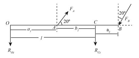
Figure (1)
Write the force component at point A along y-axis.
Write the force component at point B along y-axis.
Write the deflection equation along y-axis for beam 6 and beam 10 using Table A-9.
Here, the force component at point A along y-axis is
Write the expression for net slope of the shaft along z-axis at point O.
Substitute
Substitute
The free body diagram of the beam in the direction of z-axis is shown below.
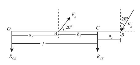
Figure (2)
Write the force component at point A along z-axis.
Write the force component at point B along z-axis.
Write the deflection equation along z-axis for beam 6 and beam 10 using Table A-9.
Here, the force component at point A along z-axis is
Write the expression for net slope of the shaft along y-axis at point O.
Substitute
Substitute
Write the expression for the net slope at point O.
Write the deflection equation along y-axis for section AC for beam 6 and beam 10 using Table A-9.
Here, the location of point A from point O is
Write the expression for net slope of the shaft along z-axis at point C.
Substitute
Substitute
Write the deflection equation along z-axis for section AC for beam 6 and beam 10 using Table A-9.
Write the expression for net slope of the shaft along z-axis at point C.
Substitute
Substitute
Write the expression for the net slope at point C.
Conclusion:
Substitute
Substitute
Substitute
Thus, the slope of the shaft at bearing point O along z-axis is
Substitute
Thus, the slope of the shaft at bearing point O along y-axis is
Substitute
Thus, the net slope of the shaft at bearing point O is
Substitute
Thus, the slope of the shaft at bearing point C along z-axis is
Substitute
Thus, the slope of the shaft at bearing point O along y-axis is
Substitute
Thus, the net slope of the shaft at bearing point C is
Want to see more full solutions like this?
Chapter 4 Solutions
Shigley's Mechanical Engineering Design (McGraw-Hill Series in Mechanical Engineering)


- The cantilever beam ACB shown in the figure has moments of inertia /, and I{in parts AC and CB, respectively. Using the method of superposition, determine the deflection 8Bat the free end due to the load P. Determine the ratio r of the deflection 8Bto the deflection S:at the free end of a prismatic cantilever with moment of inertia /] carrying the same load. Plot a graph of the deflection ratio r versus the ratio 12 //L of the moments of inertia. (Let /, II- vary from I to 5.)arrow_forwardRepeat Problem 11.3-9. Use two C 150 × 12.2 steel shapes and assume that E = 205 GPa and L = 6 m.arrow_forwardCompare the angle of twist 1 for a thin-walled circular tube (see figure) calculated from the approximate theory for thin-walled bars with the angle of twist 2 calculated from the exact theory of torsion for circular bars, Express the ratio 12terms of the non-dimensional ratio ß = r/t. Calculate the ratio of angles of twist for ß = 5, 10, and 20. What conclusion about the accuracy of the approximate theory do you draw from these results?arrow_forward
- Plot the load-deflection diagram for a pinned-end column with eccentric axial loads (see figure) if the eccentricity e of the load is 5 mm and the column has a length L = 3.6 m, moment of inertia L = 9,0 × 106 mm4, and modulus of elasticity E = 210 GPa. Note: Plot the axial load as ordinate and the deflection at the midpoint as abscissa.arrow_forwardRepeat Problem 6.2-1 but now assume that the steel plate is smaller (0.5 in. × 5 in.) and is aligned with the top of the beam as shown in the figure.arrow_forwardThe Z-section of Example D-7 is subjected to M = 5 kN · m, as shown. Determine the orientation of the neutral axis and calculate the maximum tensile stress c1and maximum compressive stress ocin the beam. Use the following numerical data: height; = 200 mm, width ft = 90 mm, constant thickness a = 15 mm, and B = 19.2e. Use = 32.6 × 106 mm4 and I2= 2.4 × 10e mm4 from Example D-7arrow_forward
- A beam with a uniform load has a sliding support at one end and spring support at the other. The spring has a stiffness k = 48EI / L3. Derive the equation of the deflection curve by starting with the third-order differential equation (the shear-force equation). Also, determine the angle of rotation θB at support B.arrow_forwardA countershaft carrying two V-belt pulleys is shown in the figure. Pulley A receives power from a motor through a belt with the belt tensions shown. The power is transmitted through the shaft and delivered to the belt on pulley B. Assume the belt tension on the loose side at B is 15 percent of the tension on the tight side. For the steel countershaft shown in the figure below, find the deflection and slope of the shaft at point A. Use superposition with the deflection equations in Table A-9. Assume the bearings constitute simple supports. In the figure shown below, Tx= 330 lbf, Ty= 50 lbf, and the diameter of the shaft (dshaft) = 1.07 in. y Tx dshaft 6 dia. Ty 8 dia. The deflection at point A is The slope at point A is rad. in.arrow_forwardFor the beam shown, determine the support reactions using singularity functions and procedure 1 from Section 4–10. Problem 4-118 Aarrow_forward
 Mechanics of Materials (MindTap Course List)Mechanical EngineeringISBN:9781337093347Author:Barry J. Goodno, James M. GerePublisher:Cengage Learning