
Concept explainers
Videos
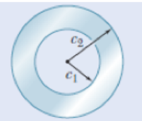
Fig. P3.30
3.30 (a) For a given allowable shearing stress, determine the ratio T/w of the maximum allowable torque T and the weight per unit length w for the hollow shaft shown, (b) Denoting by (T/w)0 the value of this ratio for a solid shaft of the same radius express the ratio T/w for the hollow shaft in terms of (T/w)0 and c1/c2 ■
(a)
The ratio
Answer to Problem 30P
The ratio
Explanation of Solution
Given information:
The maximum allowable torque is T.
The weight per unit length of the hollow shaft is w.
Calculation:
The torsion formula for allowable shear stress in the hollow shaft
Here,
The polar moment of inertia for a hollow shaft
The area of the hollow shaft is
Substitute
Let the specific weight of the shaft be
Total weight of the shaft is
The weight per unit length of the hollow shaft is expressed as follows:
Find the ratio of
Therefore, the ratio
(b)
The ratio
Answer to Problem 30P
The ratio
Explanation of Solution
Given information:
The maximum allowable torque is T.
The weight per unit length of the hollow shaft is w.
Calculation:
The polar moment of inertia for a solid shaft
The area of the solid shaft is
Substitute
The weight per unit length of the solid shaft is expressed as follows:
Find the ratio of solid shaft
Refer part (a).
The ratio
Substitute
Therefore, the ratio
Want to see more full solutions like this?
Chapter 3 Solutions
Mechanics of Materials, 7th Edition


- 3.33 (a) For the solid steel shaft shown, determine the angle of twist at A. Use G = 11.2 × 10° psi. (b) Solve part a, assuming that the steel shaft is hollow with a 1.5-in. outer radius and a 0.75-in. inner radius. Fig. P3.32 1.5 in. A 3 ft T = 60 kip - in. %3D Fig. P3.33arrow_forward3.33 (a) For the solid steel shaft shown, determine the angle of twist at A. Use G = 77 GPa. (b) Solve part a, assuming that the steel shaft is hollow with a 15 mm outer radius and a 10 mm inner radius. 15 mm A 1.8 m T = 250 N. m Fig. P3.33arrow_forward3.23 Under normal operating conditions a motor exerts a torque of magnitude T: at F. The shafts are made of a steel for which the allowable shearing stress is 82 MPa and have diameters dcDE = 24 mm and dran = 20 mm. Knowing that rp = 165 mm and rg = 114 mm, determine the largest allowable value of Tr. F. C T; B TEV E Fig. P3.23arrow_forward
- 3.46 The electric motor exerts a torque of 800 N · m on the steel shaft ABCD when it is rotating at a constant speed. Design specifications require that the diameter of the shaft be uniform from A to D and that the angle of twist between A and D not exceed 1.5°. Knowing that Tmas s 60 MPa and G = 77 GPa, determine the minimum diameter shaft that can be used. 300 N- m 500 N- m 04 m 0.6 m 0.3 m Fig. P3.46arrow_forwardPROBLEM 3.52 A 4 kNm torque T is applied at end A of the composite shaft shown. Knowing that the shear modulus is 77 GPa for the steel and 27 GPa for the aluminium, determine (a) the maximum shear stress in the steel core, (b) the maximum shear stress in the aluminium jacket, and (c) the angle of twist at A. [Ans. (a) 73.6 MPa (b) 34.4 MPa (c) 5.07°] 72 mm 54 mm 2.5 m Steel core Aluminium jackeť Fig. P3.52 and P3.53 22:37 e dx D 14/04/2022 BANG & OLUFSEN 40 delete home end pg up pg dn num backspace lock W ERT U %23 home og up 4.arrow_forwardPROBLEM 3.52 A 4 kNm torque T is applied at end A of the composite shaft shown. Knowing that the shear modulus is 77 GPa for the steel and 27 GPa for the aluminium, determine (a) the maximum shear stress in the steel core, (b) the maximum shear stress in the aluminium jacket, and (c) the angle of twist at A. [Ans. (a) 73.6 MPa (b) 34.4 MPa (c) 5.07°] Hint: angle of twist at 72 mm end A is same for core and jacket 54 mm A 2.5 m Steel core Aluminium jacket Fig. P3.52 and P3.53 22:35 BANG & OLUFSEN delete home end og up pg dn num backspace 4 lock Q WE T U 080 home pg uparrow_forward
- Equal torques T = 5 kip · ft are applied to the two steel bars with the cross sections shown. (Note that the cross-sectional areas of the bars are equal.) The length of each bar is 8 ft. Calculate the maximum shear stress and angle of twist for each bar. Use G= 12 × 10° psi for steel. 5 in. 10 in. 2 in. 1.0 in. (a) (b) FIG. P3.52arrow_forward5 The two solid shafts are connected by gears as shown and are made of a steel for which the allowable shearing stress is 50 MPa. Knowing the diameters of the two shafts are, respectively, dạc = 40 mm and def = 30 mm, determine the largest torque Tc that can be applied at C. 100 mm- B Tc 60 mm Fig. P3.25arrow_forwardas shown, determine the angle of twist between (a) B and C, 3.35 The electric motor exerts a 500 N•m-torque on the aluminum shaft ABCD when it is rotating at a constant speed. Knowing that G = 27 GPa and that the torques exerted on pulleys B and C are as shown, determine the angle of twist between (a) R are 300 N. m 200 N - m 4S min 0.9 m B 44 mm 1.2 m 40 mm Fig. P3.35arrow_forward
- 3.13 The torques T and 2T are carried by a shaft consisting of steel and aluminum segments. If the working shear stresses are 14 000 psi for steel and 7500 psi for aluminum, and the angle of rotation at the free end must not exceed 8, find the largest allowable value of T. For steel, use G = 12 x10^6 psi, and for aluminum, use G = 4 x10^6psi. T Aluminum 1.5 in.- 27/ Steel 2 in. + گری برای Happy 2 ft 3 ft as 3.14 T angle showrarrow_forward3.6 Two forces, each of magnitude P, are applied to the wrench. The diameter of the steel shaft AB is 20 mm. Determine the largest allowable value of P if the shear stress in the shaft is not to exceed 120 MPa and its angle of twist is limited to 7°. Use G= 80 GPa for steel. 300 mm B 500 mm FIG. P3.6arrow_forward3.39 The solid spindle AB has a diameter d. = 40 mm and is made of a steel with G = 77 GPa and Tal = 120 MPa, while sleeve C) is made of a brass with G = 39 GPa and Ln = 70 MPa, Determine (a) the largest torque T that can be applied at A if the given allow- able stresses are not to be exceeded and if the angle of twist of sleeve CD is not to exceed 0.375°, (b) the corresponding angle through which end A rotates. %3D 70 MPa. Determine %3D B - 15 mm 200 mm = 6 mm D 100 mm A T Fig. P3.39arrow_forward
 Elements Of ElectromagneticsMechanical EngineeringISBN:9780190698614Author:Sadiku, Matthew N. O.Publisher:Oxford University Press
 Mechanics of Materials (10th Edition)Mechanical EngineeringISBN:9780134319650Author:Russell C. HibbelerPublisher:PEARSON
 Thermodynamics: An Engineering ApproachMechanical EngineeringISBN:9781259822674Author:Yunus A. Cengel Dr., Michael A. BolesPublisher:McGraw-Hill Education
 Control Systems EngineeringMechanical EngineeringISBN:9781118170519Author:Norman S. NisePublisher:WILEY
 Mechanics of Materials (MindTap Course List)Mechanical EngineeringISBN:9781337093347Author:Barry J. Goodno, James M. GerePublisher:Cengage Learning
 Engineering Mechanics: StaticsMechanical EngineeringISBN:9781118807330Author:James L. Meriam, L. G. Kraige, J. N. BoltonPublisher:WILEY