
Applied Statics and Strength of Materials (6th Edition)
6th Edition
ISBN: 9780133840544
Author: George F. Limbrunner, Craig D'Allaird, Leonard Spiegel
Publisher: PEARSON
expand_more
expand_more
format_list_bulleted
Concept explainers
Videos
Textbook Question
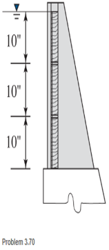
Chapter 3, Problem 3.70SP
Plank, 2 in. by 10 in. in cross section and 5 ft long, are used at the top of a dam to control the level of the impounded water, as shown. Find the resultant force (magnitude and location) on each plank.
Expert Solution & Answer
Want to see the full answer?
Check out a sample textbook solution
Students have asked these similar questions
A face of a dam adjacent to the water has the shape of an isosceles trapezoid of altitude 20 m, upper base 50 m, and the lower base 40 m. Find the total force exerted by the water on the dam when the water is 15 m deep.
A dam consists of a vertical concrete wall 8 ft high. When the water in
front of the wall is 6 ft deep, what is the maximum moment tending to overturn
the dam?
If the centers of gravity of the given plane surfaces are submerged 6 ft
The depth of V-Shape gate water channel
which incline at angle 29 ° is 2 m as shown
in the following figure. Calculate the
magnitude of the resultant force ( Fr) in KN
which acts on its inclined surface if the
depth of the channel h is 1 m.
2m
R.S.V
E.V
Chapter 3 Solutions
Applied Statics and Strength of Materials (6th Edition)
Ch. 3 - through 3.3 Determine the magnitude, direction,...Ch. 3 - Determine the magnitude, direction, and sense of...Ch. 3 - Determine the magnitude, direction, and sense of...Ch. 3 - Solve Problem 3.1 through 3.3 using the method of...Ch. 3 - Solve Problem 3.1 through 3.3 using the method of...Ch. 3 - through 3.6 Solve Problem 3.1 through 3.3 using...Ch. 3 - The 150-lb force shown is the resultant of two...Ch. 3 - Find the resultant force P exerted on the tree.Ch. 3 - Find the resultant force R exerted on the pole.Ch. 3 - Calculate the resultant force on the screw eye....
Ch. 3 - Determine the resultant of the coplanar concurrent...Ch. 3 - Use the parallelogram law to find the following...Ch. 3 - Prob. 3.13PCh. 3 - Determine the resultant of the coplanar concurrent...Ch. 3 - The resultant of the concurrent force system shown...Ch. 3 - Three force of 900 lb, 1000 lb, and 600 lb are...Ch. 3 - The four forces shown hade parallel lines of...Ch. 3 - Three coplanar concurrent forces act as shown. a....Ch. 3 - Four coplanar concurrent forces act as shown a....Ch. 3 - Determine the resultant of the four forces of...Ch. 3 - For the concrete wall and footing shown: a....Ch. 3 - Calculate the moment of the 550-lb force about...Ch. 3 - In Problem 3.22 , calculate the moment about point...Ch. 3 - Compute the moment about point A for the linkage...Ch. 3 - Compute the moment of the force F about point A...Ch. 3 - Determine the magnitude of the resultant of the...Ch. 3 - Determine the magnitude of the resultant of the...Ch. 3 - Determine the magnitude of the resultant of the...Ch. 3 - Determine the magnitude of the resultant of the...Ch. 3 - Determine the resultant and its location for the...Ch. 3 - Compute the magnitude, sense, and location of the...Ch. 3 - Compute the magnitude, sense, and location of the...Ch. 3 - Compute the magnitude and location of the...Ch. 3 - Determine the magnitude and location of the...Ch. 3 - Fresh water is impounded behind a dam to a height...Ch. 3 - Determine the magnitude and location of the...Ch. 3 - Determine the magnitude and location of the...Ch. 3 - Compute the magnitude and direction of the...Ch. 3 - Compute the magnitude and direction of the...Ch. 3 - Compute the magnitude and direction of the...Ch. 3 - A body is subjected to the following three...Ch. 3 - Determine the magnitude, direction, and sense of...Ch. 3 - Determine the magnitude, direction, and sense of...Ch. 3 - Determine the resultant of the load system shown....Ch. 3 - For the concrete structure shown, determine the...Ch. 3 - For the following computer problems, any...Ch. 3 - For the following computer problems, any...Ch. 3 - For the following computer problems, any...Ch. 3 - 3.49 Determine the magnitude, direction, and sense...Ch. 3 - The resultant and one-component force of a...Ch. 3 - The resultant force of a concurrent force system...Ch. 3 - Determine the magnitudes of forces P1 and P2 such...Ch. 3 - The resultant force of a concurrent force system...Ch. 3 - A hockey puck is acted on simultaneously by two...Ch. 3 - Determine the resultant force for each of the...Ch. 3 - Determine the resultant force for each of the...Ch. 3 - The resultant of the three concurrent forces shown...Ch. 3 - The transmission tower shown is subjected to a...Ch. 3 - A gravity-type masonry dam, as shown, depends on...Ch. 3 - The transfomer (as shown) must be lifted...Ch. 3 - Refer to the diagram for Problem 3.60 /. Assume...Ch. 3 - The plastic barrel tent anchor of Problem 2.11...Ch. 3 - Calculate the moment of the forces shown with...Ch. 3 - Determine the magnitude and location of the...Ch. 3 - Determine the moment (about point A) of the appied...Ch. 3 - The lift force on the wing of an aircraft is...Ch. 3 - A beam is subjected to distributed loads as shown....Ch. 3 - For the concrete gravity wall shown, determine the...Ch. 3 - Fresh water is impounded to a height of 8 ft...Ch. 3 - Plank, 2 in. by 10 in. in cross section and 5 ft...Ch. 3 - a. Compute the moment (about point A) of the...Ch. 3 - Determine the resultant of the three forces acting...Ch. 3 - a. Calculate the moments about points A and B due...Ch. 3 - Determine the magnitude of F1 and F2 shown such...Ch. 3 - Calculate the magnitude, direction, and sense of...
Knowledge Booster


Learn more about
Need a deep-dive on the concept behind this application? Look no further. Learn more about this topic, mechanical-engineering and related others by exploring similar questions and additional content below.Similar questions
- Find the internal force systems acting on sections 1 and 2.arrow_forwardThe corner plate of the ship's hull is bent at a radius of 1.5 meters, following the arc of a circle. What is the magnitude of the force applying on the curved corner plate for 1 meter length of the hull section if the bottom of the hull is 4.3 m below the seawater (S.G. = 1.03) surface?arrow_forwardA concrete dam with a triangular cross section is shown. Calculate (a) the total hydrostatic force on the dam due to the water if it is 800 ft wide and (b) the slanting height for the hydrostatic force intersect with the dam. Use Ywater = 64 lbf/ft³. Answers: F = and Yp = 200 ft Concrete dam 150 ft- Waterarrow_forward
- Various distributed forces are exerted on the beam shown, w(x) = 2.234 F N/m, p(x) = 1.551 N/m, q(x) = 2.071 N/m, a = 3 m, b = 5 m, and c = 5 m. Determine the net force on them and their direction (+ up. - down). State your answer in kN to 3 significant figures after correct rounding. w (x) a p(x) b q (x)arrow_forwardThe scow is 40 ft long, 20 ft wide, and 8 ft deep. It has a draft of 5 ft when floating in an upright position. The center of gravity of the scow is on the axis of symmetry, 1 ft above the water surface. Compute (a)the initial metacentric height and (b) the righting moment in freshwater when the angle of the heel is 10° *NOTE: use Fb=W to solve for the weightarrow_forwardFind the fluid force on the vertical side of the tank, where the dimensions are given in feet. Assume that the tank is full of water. (The weight-density of water is 62.4 pounds per cubic foot.) Ib Trapezoid 4 6 2 Show My Work (Required) 3arrow_forward
- (b) A sector gate is used as a control of the flow of water in a horizontal channel. The radius of the gate is 3 m and the width of the gate is 5 m. Find the magnitude of the force on the gate for the conditions shown. What angle will the resultant force make with the horizontal? = 3 = A B 1 m Horizontal axle 30 60 30° Empty Earrow_forward(c) Determine the magnitude and location of the resultant force acting on the vertical wall shown using pressure prism concept (width = 1.0 m). What is the limitation of using this concept? Patm 1.0 m Oil (0.9) Water (1.0) 1.5 marrow_forwardCalculate the horizontal and vertical components of the hydrostatic thrust on the 90 cm radius cylindrical cover in the figure for the unit cover depth. Find the resultant force for the 3m cover depth.γwater= 9.810 kN/m3arrow_forward
- Solve the horizontal hydrostatic force at AB, the vertical and horizontal force at BC, and the horizontal force at CD using the general solution. Be sure to include the diagrams in determining the hydrostatic force components.arrow_forwardQ6/ A tank wall has the shape shown in Fig. Determine the horizontal and vertical Water Tank wall components of the force of the water on a4 -ft length of the curved section AB. 18 ft 6 ftarrow_forwardCalculate the horizontal and vertical components of the hydrostatic thrust on the 90 cm radius cylindrical cover in the figure for the unit cover depth. Find the resultant force for the 3m cover depth. γwater= 9.810 kN/m3arrow_forward
arrow_back_ios
SEE MORE QUESTIONS
arrow_forward_ios
Recommended textbooks for you
 International Edition---engineering Mechanics: St...Mechanical EngineeringISBN:9781305501607Author:Andrew Pytel And Jaan KiusalaasPublisher:CENGAGE L
International Edition---engineering Mechanics: St...
Mechanical Engineering
ISBN:9781305501607
Author:Andrew Pytel And Jaan Kiusalaas
Publisher:CENGAGE L
Engineering Basics - Statics & Forces in Equilibrium; Author: Solid Solutions - Professional Design Solutions;https://www.youtube.com/watch?v=dQBvQ2hJZFg;License: Standard YouTube License, CC-BY