
Tutorials in Introductory Physics
1st Edition
ISBN: 9780130970695
Author: Peter S. Shaffer, Lillian C. McDermott
Publisher: Addison Wesley
expand_more
expand_more
format_list_bulleted
Concept explainers
Videos
Textbook Question
Chapter 22.2, Problem 1bTH
Suppose the loop were replaced by a second loop that is identical to the first except for a small cut in it (as shown). The loop is rotated as before.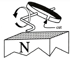
- How does the maximum induced emf in the uncut loop compare to the maximum induced emf in the cut loop? Explain.
- How does the maximum induced current in the uncut loop compare to the maximum induced current in the cut loop? Explain your reasoning.
Expert Solution & Answer

Trending nowThis is a popular solution!

Learn your wayIncludes step-by-step video

schedule01:13
Students have asked these similar questions
As shown below, a wire loop is immersed in a constant uniform B-field (all across the screen & beyond) that is pointing down. The loop's area is
increasing and the loop is not moving. Determine the direction of the induced B-field at the center of the loop & the direction of the induced
current in the loop..
B.
Direction of induced B-field at center of loop = Choose direction vX
Direction of induced current
Choose direction
loop
A 8-turn generator coil with area 0.155 m^2 rotates in a 1.20 T magnetic field. At what frequency should the coil rotate to produce a peak emf of 150, expressed four sig figs with approp units.
Attached are self notes. If you help me with the symbology... I know that f = frequency. I am not at clear the other symbols.
The problem below explores the basic principles behind electric generators, which we will discuss in class in detail.
A 505 turn circular loop coil with a diameter of 3.9cm is initially held perpendicular to the Earth's magnetic field. The coil is then rotated in 7.6ms by 90 degrees, so the plane of the coil is parallel to the magnetic field. The average emf induced in the coil is 7.2V. Find the value of the Earth's magnetic field (in T) inducing the current in the coil.As an approximation, assume that the magnetic flux in the coil changes at a constant rate between its maximum and minimum values.
Note that (see the previous problem) the flux through the coil is 505 times larger than if it was made out of one wire loop.
Chapter 22 Solutions
Tutorials in Introductory Physics
Ch. 22.1 - Use Lenz’ law to predict whether current will flow...Ch. 22.1 - For each of the cases in which you predicted that...Ch. 22.1 - Suppose that the radius of the loop were...Ch. 22.1 - Check your answer regarding the direction of the...Ch. 22.1 - Find: the direction of the magnetic moment of the...Ch. 22.1 - A copper wire loop is initially at rest in a...Ch. 22.2 - On the two diagrams below, indicate the direction...Ch. 22.2 - Suppose the loop were replaced by a second loop...Ch. 22.2 - Five loops of copper wire of same gauge...Ch. 22.2 - Five loops of copper wire of same gauge...
Additional Science Textbook Solutions
Find more solutions based on key concepts
3. What is free-fall, and why does it make you weightless? Briefly describe why astronauts are weightless in th...
The Cosmic Perspective
What is the fundamental source of electromagnetic radiation?
Conceptual Integrated Science
7.2 • BIO How High Can We Jump? The maximum height a typical human can jump from a crouched start is about 60 c...
University Physics (14th Edition)
31. (II) Your grandfather clock's pendulum has a length of 0.9930 m. If the clock runs slow and loses 21 s per ...
Physics: Principles with Applications
Knowledge Booster


Learn more about
Need a deep-dive on the concept behind this application? Look no further. Learn more about this topic, physics and related others by exploring similar questions and additional content below.Similar questions
- A rectangular loop of sides I and w moves at speed v with respect to a long straight wire with current I as shown in the diagram below. Find the voltage induced around the loop at the time when the lower side of the loop is a distance a from the straight wire loop a Iarrow_forwardInsect “zappers” use a high voltage to electrocute insects. One such device uses an AC voltage of 4320 V, which is obtained from a standard 120-V outlet by means of a transformer. a. If the primary coil has 21 turns, how many turns are in the secondary coil? b. What is the ratio of the current in the primary to current in the secondary? PLEASE SHOW ALL WORK!! Thank you!!arrow_forwardThe loop in the figure below is rotated out of the plane of the drawing while B is kept constant. You can assume the rotation axis is along the horizontal direction in the figure. a) Does the magnitude of the flux through the loop increase or decrease with time? (Assume the loop has not had time to rotate by more than 90°.) Increase/Decrease? b) If the loop has only rotated a small amount, will the induced current be clockwise or counterclockwise?arrow_forward
- JUST part A and B. Please SHOW WORK and use Vs/Ns = Vp/Np and Ip * Vp = Is * Vs %3D The primary coil of an ideal transformer is connected to a 120-V source and draws 1.0 A. The secondary coil has 600 turns and supplies an output current of 8.0 A to run an electrical device. Part A What is the voltage across the secondary coil? Part B How many turns are in the primary coil? Part C If the maximum power allowed by the device (before it is destroyed) is 210 W , what is the maximum input current to this transformer?arrow_forwardA single turn coil of radius 7.00 cm is held in a vertical plane and a magnet is rapidly moved relative to the coil as shown in the diagram below. The field inside the coil changes from 0.045 T to 0.020 T in a matter of 0.300 seconds. If the resistance of the coil is 5.00 Ohms, what is the magnitude and direction of the induced current in a coil as viewed from the side of the magnet? Make sure to include clear explanations for your choice of current direction.arrow_forwardHow (Figure 1) shows a 4.0-cm-diameter loop with resistance 0.17 Ω around a 2.0-cm-diameter solenoid. The solenoid is 11 cm long, has 100 turns, and carries the current shown in the graph (Figure 2). A positive current is cw when seen from the left. Find the current in the loop at t = 0.5 s. Express your answer as an integer and include the appropriate units. I(0.5) = Find the current in the loop at t= 1.5 s. Express your answer to two significant figures and include the appropriate units. I(1.5) = Find the current in the loop at t = 2.5 s. Express your answer as an integer and include the appropriate units. I(2.5)=arrow_forward
- In the questions below there are 6 induction processes. The circle with the dot denotes a magnetic field pointing out of and the circle with the x denotes a magnetic field pointing into the screen. A line represents a conductor, while a bar denotes a sliding conductor. An arrow labeled “v” indicates the direction in which the conductor or sliding conductor is moving. Use Lenz’s law to determine which of induced currents have a counterclockwise direction. Choose all that apply.arrow_forwardThe magnetic field through a single loop of wire 12.0 cm in radius and of 7.5 Ω resistance changes with time as shown in the figure. Calculate the emf in the loop as a function of time.What is the emf at t = 1.0 s? For the sign take the loop in the plane of the paper, and the magnetic field out of the paper. Take clockwise to be positive emf. What is the emf at t = 3.0 s? What is the emf at t = 5.0 s? What is the current at t = 1.0 s?arrow_forwardThe figure below is a top down view of a circular wire coil with rotating clockwise in a uniform magnetic field directed to the right. The position of the wire at t=to is shown as dotted lines, the position of the coil t=t is shown as a solid line. to a) Label the direction of the induced current at points A and B. b) Is the magnitude of the induced current increasing, decreasing, or constant as it moves from its position at to to t? (Tip: is the loop position headed toward I = 0 or I = Imax at t = t?) c) Label the direction of the force on the wire at points A and B. d) Will the torque on the wire speed up or slow down the angular velocity (@) of the wire?arrow_forward
- 1. The long straight wire shown in Figure 1 carries a constant current I. Justifying your answers, state the direction of the induced current (e.g., clockwise, counter clockwise, or no current) in the square conducting loop if the loop is moved (a) toward the wire, (b) away from the wire. а а I Figure 1: Problem # 1.arrow_forwardAnswer the inquiries of one of the trainees regarding the generators and transformers and their relationship with electromagnetic induction. He asked you to determine the followings: A. Briefly explain the principal operation of the generator. B. A transformer has a primary to secondary turns ratio of 1:15. Calculate the primary voltage necessary to supply a 240 V load. If the load current is 3 A determine the primary current. C. The diagram shown represents the generation of e.m.f's. Determine the following: a: The direction in which the conductor must be moved. 7 HTU. Page 8 of 12 جامعة الحسين التقنية Al Hussein Technical University D. The current direction. S Figure 3arrow_forwardA rectangular loop is placed near a long straight current-carrying wire as shown in the figure. a. Assume that we define step vectors around the loop to point counterclockwise. Is the magnetic flux ФB through the loop positive or negative? b. Calculate the magnetic flux in terms of I = |Ivector|, d, L, and W. (Hints: The magnetic field is not constant over the loop's face, so we have to actually integrate to calculate the flux. Divide the loop into thin strips. You should find that the answer is proportional to ln(d+W) / d.) c. Let the loop have resistance R. Find an expression for the current flowing in the loop as a function of dI / dt. d. If the magnitude of the current flowing in the wire is decreasing, what is the direction in which the current flows in the loop?arrow_forward
arrow_back_ios
SEE MORE QUESTIONS
arrow_forward_ios
Recommended textbooks for you
 College PhysicsPhysicsISBN:9781305952300Author:Raymond A. Serway, Chris VuillePublisher:Cengage Learning
 University Physics (14th Edition)PhysicsISBN:9780133969290Author:Hugh D. Young, Roger A. FreedmanPublisher:PEARSON
 Introduction To Quantum MechanicsPhysicsISBN:9781107189638Author:Griffiths, David J., Schroeter, Darrell F.Publisher:Cambridge University Press
 Physics for Scientists and EngineersPhysicsISBN:9781337553278Author:Raymond A. Serway, John W. JewettPublisher:Cengage Learning
 Lecture- Tutorials for Introductory AstronomyPhysicsISBN:9780321820464Author:Edward E. Prather, Tim P. Slater, Jeff P. Adams, Gina BrissendenPublisher:Addison-Wesley
 College Physics: A Strategic Approach (4th Editio...PhysicsISBN:9780134609034Author:Randall D. Knight (Professor Emeritus), Brian Jones, Stuart FieldPublisher:PEARSON
College Physics
Physics
ISBN:9781305952300
Author:Raymond A. Serway, Chris Vuille
Publisher:Cengage Learning
University Physics (14th Edition)
Physics
ISBN:9780133969290
Author:Hugh D. Young, Roger A. Freedman
Publisher:PEARSON
Introduction To Quantum Mechanics
Physics
ISBN:9781107189638
Author:Griffiths, David J., Schroeter, Darrell F.
Publisher:Cambridge University Press
Physics for Scientists and Engineers
Physics
ISBN:9781337553278
Author:Raymond A. Serway, John W. Jewett
Publisher:Cengage Learning
Lecture- Tutorials for Introductory Astronomy
Physics
ISBN:9780321820464
Author:Edward E. Prather, Tim P. Slater, Jeff P. Adams, Gina Brissenden
Publisher:Addison-Wesley
College Physics: A Strategic Approach (4th Editio...
Physics
ISBN:9780134609034
Author:Randall D. Knight (Professor Emeritus), Brian Jones, Stuart Field
Publisher:PEARSON
THE BAR MAGNET; Author: 7activestudio;https://www.youtube.com/watch?v=DWQfL5IJTaQ;License: Standard YouTube License, CC-BY