
Videos
A 250-mm-long aluminum tube (E = 70 GPa) of 36-mm outer diameter and 28-mm inner diameter can be closed at both ends by means of single-threaded screw-on covers of 1.5-mm pitch. With one cover screwed on tight, a solid brass rod (E = 105 GPa) of 25-mm diameter is placed inside the tube and the second cover is screwed on. Since the rod is slightly longer than the tube, it is observed that the cover must be forced against the rod by rotating it one-quarter of a turn before it can be tightly closed. Determine (a) the average normal stress in the tube and in the rod, (b) the deformations of the tube and of the rod.
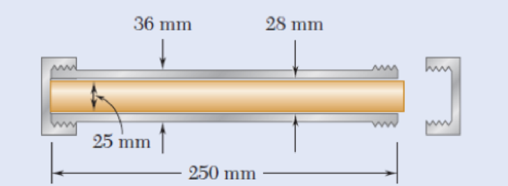
Fig. P2.16
a)
The average normal stress in the tube
Answer to Problem 16P
The average normal stress in the tube
Explanation of Solution
Given information:
The length of the tube (L) is
The outer diameter of the tube
The inner diameter of the tube
The Young’s modulus of the aluminium
The diameter of the rod
The Young’s modulus of the brass
The pitch of the single-threaded screw-on cover (p) is
The load act in the tube is P.
Calculation:
Calculate the cross sectional area of the tube
Substitute
Calculate the cross sectional area of the rod
Substitute
Calculate the deformation of the tube
Substitute
Calculate the deformation of the rod
Substitute
Calculate the deformation of the screw
Substitute
Calculate the load (P) act in the tube using the formula:
Substitute
Calculate the average normal stress in the tube
Substitute
Calculate the average normal stress in the rod
Substitute
Hence, the average normal stress in the tube
b)
The deformations of the tube
Answer to Problem 16P
The deformations of the tube
Explanation of Solution
Given information:
The length of the tube (L) is
The outer diameter of the tube
The inner diameter of the tube
The Young’s modulus of the aluminium
The diameter of the rod
The Young’s modulus of the brass
The pitch of the single-threaded screw-on cover (p) is
The load act in the tube is P.
Calculation:
Calculate the cross sectional area of the tube
Substitute
Calculate the cross sectional area of the rod
Substitute
Calculate the deformation of the tube
Substitute
Calculate the deformation of the rod
Substitute
Calculate the deformation of the screw
Substitute
Calculate the load (P) act in the tube using the formula:
Substitute
Calculate the deformations of the tube
Substitute
Calculate the deformations of the rod
Substitute
Hence, the deformations of the tube
Want to see more full solutions like this?
Chapter 2 Solutions
Mechanics of Materials, 7th Edition


- A 20 mm diameter steel rod passes concentrically through a bronze tube (200+SN) mm long, 50 mm external diameter and 40 mm internal diameter. The ends of the steel rod are threaded and provided with nuts and washers which are adjusted initially so that there is no end play at 25°C.. 1. Assuming that there is no change in the thickness of the washers, if the stress produced in the steel is (200+SN) MN/m2 when one of the nuts is tightened, the pitch of the thread being 1 mm. Find the number of turns for the nut and stress in bronze tube.2. If the temperature of the steel and bronze is then raised to 4O°C find the changes that will occur in the stresses in both materials. The coefficient of linear expansion per C is 10 x10-6 for steel and 17 x10-6 for bronze. E for steel = 210 GN/m2. E %3D for bronze = 100 GN/m2.. Note: SN = %3D Student number Student Number =32arrow_forwardPROBLEM 3. A double-row butt joint is used as a connection. It is made up of two 210-mm by 20-mm cover plates and 210-mm by 35-mm main plate. The plates are to be connected by 32-mm diameter rivets. The allowable stresses are 75MPa for shear, 90MPa for tension and 285MPa bearing. Assume that each hole is 3mm larger than the rivet diameter. ust PDF ng imen GIBL o Alel 1. What is the largest value of P (kN) that can be applied without exceeding the ollowable stress for shear? 2. What is the largest value of P (kN) that can be applied without exceeding the ollowable stress for bearing? 3. What is the largest value of P (kN) that can be applied withour exceeding the allowable stress for tension? ng inarrow_forwardThe axial stresses are 12 MPa C in the wood post B and 150 MPa T in the steel bar A as shown below. Pins at A, C, and D are smooth. Determine (a)The load P.(b)The minimum diameter for pin C if it is in single shear and the cross-shearing stress is limited to 70 MPa.(c)The minimum diameter for pin D if it is in double shear and the cross-shearing stress is limited to 70 MPa.arrow_forward
- The solid steel rod (1) has an allowable shear stress of 13 ksi. The brass tube (2) has an allowable shear stress of 5 ksi. The diameter of the rod is d1 = 0.500 in. The outside diameter of the tube is D2 = 1.625 in., and its wall thickness is t2 = 0.125 in. The tube is attached to a fixed plate at C, and both the rod and the tube are welded to a rigid end plate at B. Determine the largest torque Tmax that can be applied at the upper end of the steel rod. | T Rod (1) Fixed plate Tube (2) B End plate D2 Answer: Tmax Ib-in.arrow_forwardSnap fits are commonly used to lock plastic parts together. A design for a torsional snap- fit is shown. The rod ABC is fixed at both ends and a tab is attached to the rod pivots under the action of forces shown. The rod diameter is 7mm and G-4 GPa. Treat the tabs as rigid. Li-60mm, L2-40mm, w-30mm. (a) Determine the rotation of the cross-section B and the displacement of end D if the force F-8N. (b) Determine the maximum shear stress in the rod (Note: the latter two diagrams are to help you conceptualize.) DE W В THE F Tc ТА A Tоarrow_forwardA 13-mm-diameter steel (E = 193 GPa) rod (2) is connected to a 27-mm-wide by 10-mm-thick rectangular aluminum (E = 72 GPa) bar (1), as shown. Assume L1 = 0.74 m and L2 = 1.38 m. Determine the force P (in kN rounded to the nearest tenths) required to stretch the assembly 8.1 mm.arrow_forward
- A circular steel bar 50 mm diameter and 200 mm long is welded perpendicularly to a steel plate to form a cantilever to be loaded with 5 kN at the free end. Determine the size of the weld, assuming the allowable stress in the weld as 100MPa.arrow_forwardAxial loads are applied with rigid bearing plates to the solid cylindrical rods shown. The normal stress in aluminum rod (1) must be limited to 19 ksi, the normal stress in brass rod (2) must be limited to 23 ksi, and the normal stress in steel rod (3) must be limited to 12 ksi. Determine the minimum diameter required for each of the three rods. Assume P = 8 kips, Q = 6 kips, R = 20 kips and S = 21 kips. A D First: Calculate the internal force (positive if tensile, negative if compresive) in rod (1). Use a FBD cutting through the rod in the section that includes the free end A. Answer: F₁ = i kips. (2) (3) O B Carrow_forwardAxial loads are applied with rigid bearing plates to the solid cylindrical rods shown. The normal stress in aluminum rod (1) must be limited to 19 ksi, the normal stress in brass rod (2) must be limited to 24 ksi, and the normal stress in steel rod (3) must be limited to 12 ksi. Determine the minimum diameter required for each of the three rods. Assume P = 9 kips, Q = 4 kips, R = 18 kips and S = 21 kips.Calculate the internal force (positive if tensile, negative if compresive) in rod (1). Use a FBD cutting through the rod in the section that includes the free end A.arrow_forward
- Axial loads are applied with rigid bearing plates to the solid cylindrical rods shown. The normal stress in aluminum rod (1) must be limited to 19 ksi, the normal stress in brass rod (2) must be limited to 24 ksi, and the normal stress in steel rod (3) must be limited to 12 ksi. Determine the minimum diameter required for each of the three rods. Assume P = 9 kips, Q = 4 kips, R = 18 kips and S = 21 kips. Calculate the internal force (positive if tensile, negative if compresive) in rod (1). Use a FBD cutting through the rod in the section that includes the free end A.Answer: F1 = ? kips.arrow_forwardAxial loads are applied with rigid bearing plates to the solid cylindrical rods shown. The normal stress in aluminum rod (1) must be limited to 20 ksi, the normal stress in brass rod (2) must be limited to 24 ksi, and the normal stress in steel rod (3) must be limited to 12 ksi. Determine the minimum diameter required for each of the three rods. Assume P = 8 kips, Q = 5 kips, R = 20 kips and S = 28 kips. Calculate F1, F2, F3 and..arrow_forwardAxial loads are applied with rigid bearing plates to the solid cylindrical rods shown. The normal stress in aluminum rod (1) must be limited to 19 ksi, the normal stress in brass rod (2) must be limited to 22 ksi, and the normal stress in steel rod (3) must be limited to 13 ksi. Determine the minimum diameter required for each of the three rods. Assume P = 7 kips, Q = 2 kips, R = 16 kips and S = 20 kips.arrow_forward
 Elements Of ElectromagneticsMechanical EngineeringISBN:9780190698614Author:Sadiku, Matthew N. O.Publisher:Oxford University Press
 Mechanics of Materials (10th Edition)Mechanical EngineeringISBN:9780134319650Author:Russell C. HibbelerPublisher:PEARSON
 Thermodynamics: An Engineering ApproachMechanical EngineeringISBN:9781259822674Author:Yunus A. Cengel Dr., Michael A. BolesPublisher:McGraw-Hill Education
 Control Systems EngineeringMechanical EngineeringISBN:9781118170519Author:Norman S. NisePublisher:WILEY
 Mechanics of Materials (MindTap Course List)Mechanical EngineeringISBN:9781337093347Author:Barry J. Goodno, James M. GerePublisher:Cengage Learning
 Engineering Mechanics: StaticsMechanical EngineeringISBN:9781118807330Author:James L. Meriam, L. G. Kraige, J. N. BoltonPublisher:WILEY