
Videos
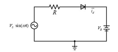
Consider the circuit in Figure 2.4. The input voltage is
a.
The minimum value of the resistance of a battery charger circuit for a given peak battery charging current.
Answer to Problem 2.1TYU
Minimum resistance is
Explanation of Solution
Given Information:
The given values are:
Range of voltage
Calculation:
The battery charger circuit contains a half-wave rectifier as shown below.

Using the Kirchhoff’s Voltage Law, voltage across the resistor is given by,
The current through the resistor,
The peak current through the resistor (or the diode),
The diode current will be maximum when the input voltage is maximum at
From equation (1)
Then, equation (2) can be written as,
Then the minimum value of the resistor,
Substituting the values,
Conclusion:
The minimum resistance value is
b.
The range in peak current and the range in a fraction of cycle diode conducts.
Answer to Problem 2.1TYU
The range in peak current is,
The range in duty cycle is
Explanation of Solution
Given Information:
Calculation:
Here the battery charger circuit contains a halfwave rectifier and the circuit can be drawn as below. The range for the battery voltage is
Using the Kirchhoff’s Voltage Law,
It is known that,
The voltage through the resistor,
Then equation (1) can be written as,
The range for the peak current through the diode,
When the diode is forward biased and at the time diode start conducting, let’s say
Substitute the values
By symmetry, the point where
Then fraction of the time diode is conducting can be calculated as,
Hence,
Conclusion:
The range in peak current is,
The range in the duty cycle is
Want to see more full solutions like this?
Chapter 2 Solutions
Microelectronics: Circuit Analysis and Design
Additional Engineering Textbook Solutions
Principles Of Electric Circuits
Electric machinery fundamentals
Fundamentals of Applied Electromagnetics (7th Edition)
Basic Engineering Circuit Analysis
Engineering Electromagnetics
Electric Circuits (10th Edition)


- Vs is a 20 V peak-to-peak, 250Hz (that is 4 mS time period) triangular wave in the circuit below. Select the correct output voltage wave signal info(VO). (Use ideal diode model). Vs ww 1 ΚΩ O The Output voltage clips at +10V O The output voltage clips at -10V O None of the above ID 10 V- + Vo O The output voltage signal is same as input signal when input goes above +10Varrow_forward//sketch the output wave form of the below. The input voltage circuit shown varies from "0" to "150V" linearly, Assame the diodes are ideal. D₂ Vi gül DI * + 300 - look 3200K. I+ I 10ου + vo.arrow_forwardIn the following circuit the diodes are 0.7 constant voltage model 10V Select one: C. m 10K a. None of the answers b. 2 diodes are reversely biased the 10K resistor can not have currents d. 2 diodes are forwardly biasedarrow_forward
- PROBLEM: The diode (blue line) should be at -10V not -8V SOFTWARE USED: LTspice XVII---Figure 1 is my work, and figure 2 is the correct sample. Please tell me what I did wrong. Thank you :))---Below is the .asc filehttps://www.mediafire.com/file/zxauoh86zi79nfu/EXPERIMENT_01.asc/filearrow_forwardTwo germanium diodes are connected in series and have a load resistance of 10 kQ and a forward supply voltage of 5 V. Calculate the voltage across the load resistor. * O 4.7 V O 4.4 V O 0.3 V 0.6 Varrow_forwardA simple p*n junction is designed to work as IMPATT diode. The doping concentrations in the p* layer is 1019 cm-3 while the doping in the n-layer is 0.7 x10¹⁶ Calculate the peak electric field if the breakdown voltage is 80 V and the dielectric constant is 11.9. Express your answer in the unit of kV/cm. cm-3arrow_forward
- The D diode used in the diode circuit shown in the figure is a silicon diode. a. Plot the output voltage of the circuit. b. Describe the working principle for each phase in detail R1 10 kN V out +12 V D R2 100 N Vin-15 sin(wt) R3 220 Narrow_forwardQuèstion 15 Power supply circuit is delivering 0.5 A and an average voltage 20 V to the load as shown in the circuit below. The ripple voltage of the half wave rectifier is 0.5 V and the diode is represented using constant voltage model. The smoothing capacitor value is equal to IL-DE 205A iL-DC 220V ams 5OH23 VL-DC =20V 0.01 F 0.02 F 0.0167 F None of the above SHOT ON RED MAGIC 5S POWERED BY NUBIAarrow_forwardThe anode of a diode is connected to one terminal of a 1-KΩ resistor. The other terminal of the resistor is connected to the ground and the negative terminal of a 12-volt DC source is also grounded. The three components are connected in series. How much is the load current with the ideal diode?arrow_forward
- In the figure below, how much is the total diode drop when the third approximation is used to solve for V L and I L ?arrow_forwardFull-wave rectified sine wave circuit is used to measure the RMS value of a half square wave with the help of PMMC meter. The meter was actually calibrated for sine wave. The circuit uses a meter movement with a full scale deflection current of 200uA and internal meter resistance of 5kΩ. Assuming Non-ideal diodes having resistance 1kΩ, Analyze the circuit to determine the value of series multiplier resister and the corrected RMS voltage, if meter is to read 225V RMS full-scale.arrow_forwardA clipper circuit based on diodes are simple way to modify waveform in mechatronics. Assume that the two diodes shown in the circuit below are ideal diodes. If the input voltage in the circuit is a 1 kHz sinusoid with peak amplitude of 8V, sketch the Vaue (t). 10 k. 8V 10 kN. D2 RL Vourlt) Vin= Vin(t) Ims D1 6V -8V 4V Page | 1arrow_forward
 Introductory Circuit Analysis (13th Edition)Electrical EngineeringISBN:9780133923605Author:Robert L. BoylestadPublisher:PEARSON
 Delmar's Standard Textbook Of ElectricityElectrical EngineeringISBN:9781337900348Author:Stephen L. HermanPublisher:Cengage Learning
 Programmable Logic ControllersElectrical EngineeringISBN:9780073373843Author:Frank D. PetruzellaPublisher:McGraw-Hill Education
 Fundamentals of Electric CircuitsElectrical EngineeringISBN:9780078028229Author:Charles K Alexander, Matthew SadikuPublisher:McGraw-Hill Education
 Electric Circuits. (11th Edition)Electrical EngineeringISBN:9780134746968Author:James W. Nilsson, Susan RiedelPublisher:PEARSON
 Engineering ElectromagneticsElectrical EngineeringISBN:9780078028151Author:Hayt, William H. (william Hart), Jr, BUCK, John A.Publisher:Mcgraw-hill Education,