
Concept explainers
Videos
(a)
The time required to reduce theangular velocityof cylinder A to
Cylinder A has the angular velocity of
Answer to Problem 17.75P
Time required for cylinder A to attain
Explanation of Solution
Given:
Mass of cylinder,
Radius of cylinder,
Angular velocity of cylinder
Concept used:
Impulse momentum principle.
Moment of inertia
Calculation:
According to impulse-momentum principle for cylinder B,
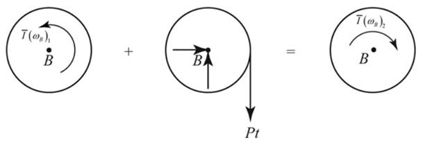
Taking moment about B,
We have,
Moment of inertia,
As per kinematics.
Considering C as aninstantenous center of cylinder A.
According to the impulse-momentum principle in cylinder A,
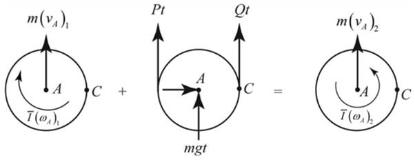
Taking moment about C,
Conclusion:
Thus we can find the time required to reduce angular velocity from
(b)
The tension in the portion of the belt connecting the two cylinders.
Answer to Problem 17.75P
Belt tension between two cylinders is
Explanation of Solution
Given:
The radius of the cylinder,
Angular velocity of cylinder
Concept used:
Impulse momentum principle
Moment of inertia
Calculation:
As per calculation is done in subpart (a),
We have,
Conclusion:
Thus the tension in belt between cylinder A and B is found to be
Want to see more full solutions like this?
Chapter 17 Solutions
Vector Mechanics For Engineers


- Gear A weighs 1 lb and has a radius of gyration of 1.3 in.; gear B weighs 6 lb and has a radius of gyration of 3 in.; gear C weighs 9 lb and has a radius of gyration of 4.3 in. Knowing a couple M of constant magnitude of 40 lb-in. is applied to gear A, determine (a) the angular acceleration of gear C, (b) the tangential force that gear B exerts on gear C. M A 2 in. 2 in. borg J 4 in. B 6 in. с w ណarrow_forwardThe blade of a portable saw and the rotor of its motor have a total weight of 2.5 lb and a combined radius of gyration of 1.5 in. Knowing that the blade rotates as shown at the rate w1= 1500 rpm, determine the magnitude and direction of the couple M that a worker must exert on the handle of the saw to rotate it with a constant angular velocity w2= -(2.4 rad/s)j.arrow_forwardIn the helicopter shown; a vertical tail propeller is used to pre- vent rotation of the cab as the speed of the main blades is changed. Assuming that the tail propeller is not operating determine the final angular velocity of the cab after the speed of the main blades has been changed from I80 to 240 rpm. (The speed of the main blades is measured relative to the cab, and the cab has a centroidal moment of inertia of 650 lb.ft.s2. Each of the four main blades is assumed to be a slender rod 14 ft weighing 55 lb.)arrow_forward
- A 40-kg flywheel of radius R = 0.5 m is rigidly attached to a shaft of radius r = 0.05 m that can roll along parallel rails. A cord is attached as shown and pulled with a force P of magnitude 150 N. Knowing the centroidal radius of gyration is k = 0.4 m, determine (a) the angular acceleration of the flywheel, (b) the velocity of the center of gravity after 5 s. 15° Parrow_forwardA 2.5-kg homogeneous disk of radius 80 mm rotates at the constant rate ω1 = 50 rad/s with respect to arm ABC, which is welded to a shaft DCE. Knowing that at the instant shown, shaft DCE has an angular velocity w2 = (12 rad/s)k and an angular acceleration a2= = (8 rad/s2)k, determine (a) the couple that must be applied to shaft DCE to produce that acceleration, (b) the corresponding dynamic reactions at D and E.arrow_forwardD C Answer: B 0.4 m- 0.4 m Two identical slender rods AB and BC are welded together to form an L-shaped assembly. The assembly is pressed against a spring at D and released from the position shown. Knowing that the maximum angle of rotation of the assembly in its subsequent motion is 58° with the horizontal (counterclockwise), determine the magnitude of the angular velocity of the assembly as it passes through the position where rod AB forms an angle of 27° with the horizontal.arrow_forward
- A 5.32-kg disk A of radius 0.445 m initially rotating counter-clockwise at 436 rev/min is engaged with a 6.72-kg disk B of radius 0.275 m initially rotating clockwise at 528 rev/min, where the moment of inertia of a disk is given as I = ½ mi?. Determine their combined angular speed (in rpm) and direction of rotation after the meshing of the two disks. Remember to show clearly the equations that you use!!'arrow_forwardEach of the gears A and B has a mass of 675 g and a radius of gyration of 40 mm, while gear C has a mass of 3.6 kg and a radius of gyration of 100 mm. Assume that kinetic friction in the bearings of gears A, B C produces couples of constant magnitude 0.15 N.m, 0.15 N.m, 0.3 N.m, respectively. Knowing that the initial angular velocity of gear C is 2000 rpm, determine the time required for the system to come to rest.arrow_forwardThe double pulley shown has a mass of 3 kg and a radius of gyration of 100 mm. Knowing that when the pulley is at rest, a force P of magnitude 24 N is applied to cord B, determine (a) the velocity of the center of the pulley after 1.5 s,(b) the tension in cord C.arrow_forward
- 3. (17.21) A collar at point C with a mass of 1 kg is rigidly attached at a distance d = 300 mm from the end of a uniform slender rod AB. The rod has a mass of 3 kg and has a length of L = 600 mm. Knowing that the rod is released from rest in the position shown, determine the angular velocity of the rod after it has rotated through 90°. Notes: Ignore rotation of the collar since its dimensions are negligible. The controidal moment of inertia of the rod is I = m[² 12 L d Position 1 Position 1 B B A Position 2 L A' ctivate Windowsarrow_forward4. The link EF of mass 2 kg is welded at point A to a link ABC of mass 2 kg, which rotates about a pivot B. A spring of constant k =300 N/m and of un-stretched length 150 mm is attached to the link ABC as shown. Knowing that in the position shown the assembly has an angular velocity of 10 rad/s clockwise, (a) Determine the angular velocity when the assembly has rotated 90° clockwise, (b) Find the corresponding angular acceleration of part (a), and (c) Find the corresponding reaction force at point B. (For (b) and (c), set up all the required equations with a Free-Body-Diagram 150 mm and a Kinetic Diagram) 150 mm, 150 mm, E 150 mm 360 mmarrow_forwardA 6-lb homogeneous disk of radius 3 in. spins as shown at the constant rate w1 = 60 rad/s. The disk is supported by the fork-ended rod AB , which is welded to the vertical shaft CBD The system is at rest when a couple M0 is applied as shown to the shaft for 3 s and then removed. Knowing that the maximum angular velocity reached by the shaft is 18 rad/s, determine (a) the couple M0) the dynamic reactions at C and D after the couple has been removed.arrow_forward
 Elements Of ElectromagneticsMechanical EngineeringISBN:9780190698614Author:Sadiku, Matthew N. O.Publisher:Oxford University Press
 Mechanics of Materials (10th Edition)Mechanical EngineeringISBN:9780134319650Author:Russell C. HibbelerPublisher:PEARSON
 Thermodynamics: An Engineering ApproachMechanical EngineeringISBN:9781259822674Author:Yunus A. Cengel Dr., Michael A. BolesPublisher:McGraw-Hill Education
 Control Systems EngineeringMechanical EngineeringISBN:9781118170519Author:Norman S. NisePublisher:WILEY
 Mechanics of Materials (MindTap Course List)Mechanical EngineeringISBN:9781337093347Author:Barry J. Goodno, James M. GerePublisher:Cengage Learning
 Engineering Mechanics: StaticsMechanical EngineeringISBN:9781118807330Author:James L. Meriam, L. G. Kraige, J. N. BoltonPublisher:WILEY