
Concept explainers
Videos
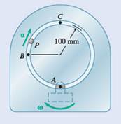
Pin P slides in a circular slot cut in the plate shown at a constant relative speed
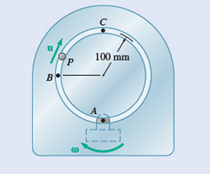
Fig. P15.173
(a)
Acceleration of pin at point A.
Answer to Problem 15.173P
The acceleration of pin P at point A is
Explanation of Solution
Given information:

Constant speed
Constant angular velocity
The Coriolis acceleration is a combination of
Where
The Coriolis acceleration is defined as,
Calculation:
Point A is the origin.
Therefore, position vector
The relative velocity
The acceleration
The relative acceleration
The Coriolis acceleration
Therefore, acceleration
Conclusion:
The acceleration of pin P at point A is
(b)
Acceleration of pin at point B
Answer to Problem 15.173P
The acceleration of pin P at point B is
Explanation of Solution
Given information:

Constant speed
Constant angular velocity
The Coriolis acceleration is a combination of
Where
The Coriolis acceleration is defined as
Calculation:
The position vector
The relative velocity
The acceleration
The relative acceleration
The Coriolis acceleration
The acceleration
Find the magnitude and angle
Conclusion:
The acceleration of pin P at point B is
(c)
Acceleration of pin at point C
Answer to Problem 15.173P
The acceleration of pin P at point C is
Explanation of Solution
Given information:
Constant speed
Constant angular velocity
The Coriolis acceleration is a combination of
Where
The Coriolis acceleration is defined as
Calculation:
The position vector
The relative velocity
The acceleration
The relative acceleration
The Coriolis acceleration
The acceleration
Conclusion:
The acceleration of pin P at point C is
Want to see more full solutions like this?
Chapter 15 Solutions
Vector Mechanics For Engineers


- The assembly shown consists of two rods and a rectangular plate BCDE that are welded together. The assembly rotates about the axis AB with a constant angular velocity of 16 rad/s. Knowing that the rotation is counterclockwise as viewed from B, determine the velocity and acceleration of corner E. 225 mm 500 mm The velocity of corner Eis ( The acceleration of corner Eis A 300 mm m/s)i + ( m/s²)i + m/s)j. | m/s²)j + m/s2)k.arrow_forwardA chain is looped around two gears of radius 40 mm that can rotate freely with respect to the 320-mm arm AB. The chain moves about arm AB in a clockwise direction at the constant rate of 80 mm/s relative to the arm. Knowing that in the position shown arm AB rotates clockwise about A at the constant rate ω = 0.75 rad/s, determine the acceleration of each of the chain links indicated Links 1 and 2.arrow_forward15.170 A basketball player shoots a free throw in such a way that his shoul- der can be considered a pin joint at the moment of release as shown. Knowing that at the instant shown the upper arm SE has a constant angular velocity of 2 rad/s counterclockwise and the forearm EW has a constant clockwise angular velocity of 4 rad/s with respect to SE, determine the velocity and acceleration of the wrist W. W 300 mm 80° Model 30 350 mm Fig. P15.170arrow_forward
- A The 18-in.-radius fly wheel is rigidly attached to a 1.5-in. -radius shaft that can roll along parallel rails. Knowing that at the instant shown the center of the shaft has a velocity of 1.2 in/s and an acceleration of 0.5 in/s?, both directed down to the left, determine the acceleration (a) of point A, (b) of point B. 18 in. 20 Вarrow_forwardThe assembly shown consists of two rods and a rectangular plate BCDE that are welded together. The assembly rotates about the axis AB with a constant angular velocity of 16 rad/s. Knowing that the rotation is counterclockwise as viewed from B, determine the velocity and acceleration of corner E. 225 mm 500 mm The velocity of corner Eis ( The acceleration of corner Eis -( 300 mm m/s)i + 1 m/s²)i + x m/s)j. /s²)j + m/s +( m/s²)k.arrow_forwardA straight rack rests on a gear of radius r= 3 in. and is attached to a block B as shown. Knowing that at the instant shown 8 = 20°, the angular velocity of gear D is 4 rad/s clockwise, and it is speeding up at a rate of 2.5 rad/s², determine the angular acceleration of AB and the acceleration of block B. The angular acceleration of AB is The acceleration of block B is rad/s² clockwise. (Round the final answer to three decimal places.) in./s2. (Round the final answer to one decimal place.)arrow_forward
- 15.168 and 15.169 A chain is looped around two gears of radius 2 in, that can rotate freely with respect to the 16-in. arm AB. The chain moves about arm AB in a clockwise direction at the constant rate of 4 in/s relative to the arm. Knowing that in the position shown arm AB rotates clockwise about A at the constant rate = 0.75 rad/s, determine the acceleration of each of the chain links indicated. @ Links 1 and 2. 15.168 15.169 Links 3 and 4. 4 8 in." Fig. P15.168 and P15.169 8 in.- B 3arrow_forwardRequired information NOTE: This is a multi-part question. Once an answer is submitted, you will be unable to return to this part. For a 5-m steel beam AE, the acceleration of point A is 2.5 m/s² downward and the angular acceleration of the beam is 1.5 rad/s2 counterclockwise. Knowing that at the instant considered the angular velocity of the beam is zero, determine the acceleration of cable B and cable D. A -1.5 m- B Determine the acceleration of cable B The acceleration of cable Bis 2 m 1.375 5 m/s2. D -1.5 m- Earrow_forwardThe elliptical exercise machine shown below has fixed axes of rotation at points A and E. Knowing that at the instant shown the flywheel AB has a constant angular velocity of 6 rad/s clockwise, determine the acceleration of point D. Solve this problem, then assuming the ease of starting the elliptical moving is proportional to the angular velocity (app) and using only the equations below plus geometry, how would you redesign the machine to minimize the effort needed to start the elliptical moving. Be sure to resolve the problem based on your redesign to show that the effort would be lowered and estimate the percent change in effort. aв = a +ax TB/A - W²TB/A VB = VA+WXTB/A 0.2 m 1.2 m 0.09 m 0.12 m 0.6 m 0.8 marrow_forward
- NOTE: This is a multi-part question. Once an answer is submitted, you will be unable to return to this part. The sprocket wheel and chain shown are being operated at a speed of 600 rpm counterclockwise. When the power is turned off, it is observed that the wheel and chain comes to rest in 4 s. 4 in. B Assuming uniformly decelerated motion, determine the magnitudes of the velocity and acceleration of point B of the wheel immediately before the power is turned off. (You must provide an answer before moving on to the next part.) The magnitudes of the velocity and acceleration of point B of the wheel are in./s and ft/s², r , respectively.arrow_forwardBoth 15-cm-radius wheels roll without slipping on the horizontal surface. Knowing that the distance AD is 12.5 cm, the distance BE is 10 cm, that D has a velocity of 30 cm/s to the right and acceleration of E is 60 cm/s? to the left, determine the angular velocity and angular acceleration of link AB, angular velocity and angular acceleration of both wheels. Also determine the acceleration of point C. | 30 y Wheel 1 45 cm Wheel 2 /A 15cm 10 cm VD=30 cm/s B aE=60 cm/s2 15 cm 12.5 cmarrow_forwardA series of small machine components are moved by means of a conveyor belt that passes over a 6-in. idler pulley. radio. At the instant shown, point A's velocity is 15 in/s to the left and its acceleration is 8 in/s² to the right. Determine the angular acceleration of the guide pulley. A 6 in. Barrow_forward
 Elements Of ElectromagneticsMechanical EngineeringISBN:9780190698614Author:Sadiku, Matthew N. O.Publisher:Oxford University Press
 Mechanics of Materials (10th Edition)Mechanical EngineeringISBN:9780134319650Author:Russell C. HibbelerPublisher:PEARSON
 Thermodynamics: An Engineering ApproachMechanical EngineeringISBN:9781259822674Author:Yunus A. Cengel Dr., Michael A. BolesPublisher:McGraw-Hill Education
 Control Systems EngineeringMechanical EngineeringISBN:9781118170519Author:Norman S. NisePublisher:WILEY
 Mechanics of Materials (MindTap Course List)Mechanical EngineeringISBN:9781337093347Author:Barry J. Goodno, James M. GerePublisher:Cengage Learning
 Engineering Mechanics: StaticsMechanical EngineeringISBN:9781118807330Author:James L. Meriam, L. G. Kraige, J. N. BoltonPublisher:WILEY