
Concept explainers
Videos
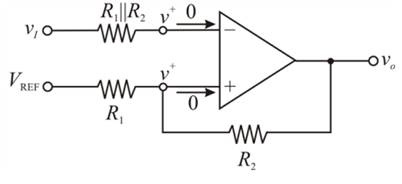
Consider the Schmitt trigger in Figure 15.30(a). (a) Derive the expressionfor the switching point and crossover voltages as given in Equations (15.76)and (15.77). (b) Let
(a)
To derive: the expression for the switching point and crossover voltages
Answer to Problem 15.49P
The switching voltage
The upper crossover voltage of Schmitt trigger is
The lower crossover voltage of Schmitt trigger is
Explanation of Solution
Given:
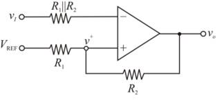
Consider the Schmitt trigger as shown below.

Calculation:
In an ideal op-amp, the inverting and non-inverting terminal currents are zero. And the inverting and non-inverting node voltages are equal. Given circuit can be represented as
Applying Kirchhoff’s current law at inverting node:
Applying Kirchhoff’s current law at non-inverting node:
Assuming
Therefore, the switching voltage
When
The upper crossover voltage off Schmitt trigger is
Therefore, the upper crossover voltage of Schmitt trigger is
When
The lower cross over voltage of Schmitt trigger is
Therefore, the lower crossover voltage of Schmitt trigger is
Conclusion:
The switching voltage
The upper crossover voltage of Schmitt trigger is
The lower crossover voltage of Schmitt trigger is
(b)
The values of
Answer to Problem 15.49P
The resistor values are
The reference voltage is
Explanation of Solution
Given:
The crossover voltages are
The minimum resistance is to be

Calculation:
Let
The minimum resistance is to be
The crossover voltages are
Substitute
Substitute
Substitute
Choose
Therefore, the resistor values are
Substitute
Substitute
Conclusion:
Therefore, the resistor values are
(c)
To find: the currents in the resistors when
Answer to Problem 15.49P
When
When
Explanation of Solution
Given:
Consider the Schmitt trigger as shown below.
Calculation:
The current in the resistor is given by
( i ) When
The current in the resistor is
Therefore, the current is
( ii ) When
The current in the resistor is
Therefore, the current is
Conclusion:
Therefore,
When
When
Want to see more full solutions like this?
Chapter 15 Solutions
Microelectronics: Circuit Analysis and Design


- Q. No 1. For the given analog signal, follow the proper steps to convert this signal to digital signal. (Take voltage levels L = 8, n= 3). Also assign proper coding to each voltage level and draw the resultant digital waveform for the given analog signal. Sample times Arnalog imput Timearrow_forward3. A full-wave zero-current switching quasi-resonant boost converter is operated at the following specification: Input voltage VS=48V, Output voltage Vo=60V Switching frequency fs=0.6MHz, Output current Io = 4A Calculate the requirement of the resonant component Lr and Cr, when the converter is just operated at the boundary of the ZCS mode. Estimate the power loss in the Lr if its series equivalent resistance is 0.1 Ω.arrow_forwardIn Steady-State Operation o f Buck DC-DC Converter Explain how the switching frequency component is eliminated by the output filter network.arrow_forward
- Explain how the Active Low Pass Filter works in detail, as shown in a drawingarrow_forwardFM modulated signal is demodulated using: Select one: O a. Discriminator O b. Discriminator followed by integrator Oc. Costas PLL O d. Carrier reinsertion methodarrow_forwardDetermine the noise power for the figure shown below. Simulation Settings SNR 31.623 SNR 15.0 dB Signal Generator - Properties Amplitude > 1.35 V Frequency > 0.2 kHz Output On Waveform Sine O a. 0.028816 mV^2 O b. 0.06075 V^2 c. 57.632 mV^2 O d, 28.816 mV^2arrow_forward
- • Design a classical rectifier to deliver 100W into a resistive load from a 120V, 60HZ mains. ac Quantify the effect for different values of filter capacitance on: >average output voltage >output voltage ripple >Input current shape, harmonic content and THDarrow_forwardA boost converter has an input voltage Vb=5V. The average load current is lo=0.5A. The switching frequency is 25 kHz. Suppose that a regulator is added (L=0.15 mH and C=0.22 mF) and that the current is continuous. If the average output voltage is Vo =15V, then the ripple current of the inductor delta() is equal to: Select one: a. 1.41A b. 0.56A O c. None of these d. 0.89Aarrow_forwardDesign a CT-FWR to supply a load of (50) with a waveform of the following specifications: - Vdc = 12 V Ripple factor = 0.1 % the main power supply is (220 Vrms, 50 Hz). Determine the following values: - 1- The value of capacitor filter. 2- The maximum load voltage (VmR) 3- The transformer turns ratio (a). 4- The RMS value of the load voltage. 5- Draw the output waveform. (assume ideal diodes)arrow_forward
- Consider the buck converter with Vin=25 V, V.=12 V at 1,=2 A, fs=50 KHz. Determine: 1. The duty cycle D 2. Lerit 3. ILmins ILmax, 1o, aves Lin, ave for L=100 Lerit 4. Output voltage ripple for C=0.47µF 5. C for |Ve = 2% of V.arrow_forwardA chopper has input voltage of 270 and the load resistance as 7N, the average load current as 53A. If the non-conducting time of thyristor chopper is 130 psec. Calculate the pulse width of output voltage in u sec. In case pulse width is halved for constant frequency operation, find new output voltage. Duty Cycle pulse width of output voltage in usec new output voltagearrow_forwardD1 D V1 D4 D2 V D D Diode Model: 1N5817 R = 10k Vi= sine (0 5 100) Given the parameters above, simulate the given circuit using .tran 0 30m 0. Solve for the output peak to peak voltage across the resistor and the output frequency measured across the resistor. Output Frequency = (When computing for the frequency, use 4v as reference point) Output Voltage (pk-pk) = + R1 R D3 Darrow_forward
 Introductory Circuit Analysis (13th Edition)Electrical EngineeringISBN:9780133923605Author:Robert L. BoylestadPublisher:PEARSON
 Delmar's Standard Textbook Of ElectricityElectrical EngineeringISBN:9781337900348Author:Stephen L. HermanPublisher:Cengage Learning
 Programmable Logic ControllersElectrical EngineeringISBN:9780073373843Author:Frank D. PetruzellaPublisher:McGraw-Hill Education
 Fundamentals of Electric CircuitsElectrical EngineeringISBN:9780078028229Author:Charles K Alexander, Matthew SadikuPublisher:McGraw-Hill Education
 Electric Circuits. (11th Edition)Electrical EngineeringISBN:9780134746968Author:James W. Nilsson, Susan RiedelPublisher:PEARSON
 Engineering ElectromagneticsElectrical EngineeringISBN:9780078028151Author:Hayt, William H. (william Hart), Jr, BUCK, John A.Publisher:Mcgraw-hill Education,