
Videos
(a)
Value of current IDQ1 and ICQ2 .
(a)
Answer to Problem 12.40P
Value of current is,
Explanation of Solution
Given:
The given values are:
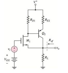
The given circuit is shown below.
Calculation:
Modified circuit diagram is shown below.
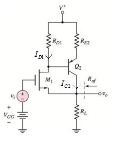
Neglecting base current.
Equation of current ID1 is,
Equation of voltage VD is,
Equation of current IC2 is,
Value of voltage VGS is,
Value of current IDQ1 is,
Value of current ICQ2 is,
(b)
Value of small signal voltage gain.
(b)
Answer to Problem 12.40P
Value of small signal voltage gain is 0.88.
Explanation of Solution
Given:
Given values are:
Calculation:
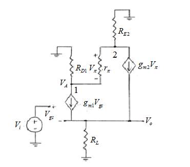
Small signal circuit is shown below.
Value of trans-conductance of transistor 1 is,
Value of trans-conductance of transistor 2,
Value of small signal resistance is,
Applying KCL at node (2),
Equation of output voltage is,
Applying KCL at node (1),
Value of small signal voltage gain is,
(c)
Value of small signal output resistance.
(c)
Answer to Problem 12.40P
Value of small signal output resistance is
Explanation of Solution
Given:
Given values are,
Calculation:
Small signal circuit for output resistance calculation ( Vi =0) is,
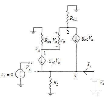
Applying KCL at node 3 for output resistance,
Want to see more full solutions like this?
Chapter 12 Solutions
Microelectronics: Circuit Analysis and Design


- (c) LVDT will be used to measure work piece motion from -1.2 cm to 1.4 cm , the static transfer function (sensitivity) =23.8 mV/mm find: 1) The voltage output range. 2) The position when V,= -300 mV. 3) If the resolution changed to 0.5 mm what will be the resolution of the output voltage.arrow_forwardIf the circuit shown in Figure #1 had a 10 kΩ resistor connected as a load resistor, RL and an input signal is applied to the base of the transistor through the coupling capacitor C1, with an amplitude of 22 mVpp at a frequency of 1 kHz. Determine the new voltage gain AV and the output voltage VOUT. Is the output signal clipped?arrow_forwardFor the common gate amplifier in the figure, V*=5 V V=-5 V Rs= 4K oVe RD= 2K SRs RD RL RL= 4K RG= 50K RoE :CG Ri= 0.5K РMOS Kp= 1 mA/V? VIP= -0.8 V 2= 0 Cg= 4 pF Cgd=1 pF a) Determine the midband voltage gain Av=vo/vi. b) Determine the upper 3 dB frequency.arrow_forward
- Question 1: Design the Feed-back bias circuit shown below. Vec = 3V, Ic = 3 mA, Vc = Vcc/2, VBE = 0.7 V, and B = 100. IBI = IB2. (hints, Fined RC, RB1 and RB2). Vcc Rc Ra R Inzarrow_forwardFor a JFET transistor, sketch the transfer curve ID = f(VGs) defined by IDSS and V₂ = +8 V = 14 mAarrow_forward10V H 500. Vos 20V 1) The datasheet for the MOSFET gives: Io(on)=500mA with Vos(on)=600mV and VGS(on)=+10V. Find Ros(on), ID, and Vos.arrow_forward
- Listen A base bias method is used in the following circuit. For Bpc = 100, the value of collector current is: +Vcc +15 V RC 1.8 k2 RB 560 k2 O 2.55 mA O 26.78 mA O 8.33 mA O 13.4 mAarrow_forwardQ-2. An-channel JFET has device parameters of Ioss = 7.5 mA and Ve = 4 V. Sketch the transfer characteristics.arrow_forward1- If you I have the following Q-point specifications VCB=6V Ic= 1.4 mA IB = 10 μA Av = 186 R₁ = 22K0 For the Common Base bias circuit shown in figure (5), design bias circuit and ensure that the Q-point in the middle of the DC load line using the required equations. Record the calculated values of the resistors i. Vcc= Iε = re= a = Av = Rc = VcB = VCE = RE Vε = IR1 = IR2 = R₂ = =arrow_forward
- Consider the Circuit shown below: Rf Ri Vin Vo Solve for the output voltage Vo in mV if Rf=13.07kOhms, Ri=3.60kOhms and Vin=2.40mV.arrow_forwardDetermine the required values of R1, R2, Rc, and RE. Also, determine the expected output voltage if the input voltage is equal to 0.001 Vrms. GIVEN: Zi = 1145.66 ohms Zo = 3.3 Kohms Beta = 80 Vcc = 20V R1 + R2 = 43.7 Kohms Av = 167.43 Ai = 58.13arrow_forwardt' 3. Predict the input signal frequencies fi and f2 for the block shown in Figure A3. A₁ sin(2af₁t) A₂ Sin (27f₂t) Figure A3 [M [R Output equation: A/2 [cos (18840t)-cos (43960t)]arrow_forward
 Introductory Circuit Analysis (13th Edition)Electrical EngineeringISBN:9780133923605Author:Robert L. BoylestadPublisher:PEARSON
 Delmar's Standard Textbook Of ElectricityElectrical EngineeringISBN:9781337900348Author:Stephen L. HermanPublisher:Cengage Learning
 Programmable Logic ControllersElectrical EngineeringISBN:9780073373843Author:Frank D. PetruzellaPublisher:McGraw-Hill Education
 Fundamentals of Electric CircuitsElectrical EngineeringISBN:9780078028229Author:Charles K Alexander, Matthew SadikuPublisher:McGraw-Hill Education
 Electric Circuits. (11th Edition)Electrical EngineeringISBN:9780134746968Author:James W. Nilsson, Susan RiedelPublisher:PEARSON
 Engineering ElectromagneticsElectrical EngineeringISBN:9780078028151Author:Hayt, William H. (william Hart), Jr, BUCK, John A.Publisher:Mcgraw-hill Education,