
Concept explainers
Videos
Coherent red light is incident on a mask with two very narrow slits a distance d apart. The photograph at right illustrates the pattern that appears on a distant screen.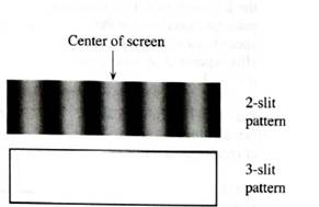
On the photograph, label each of the maxima and minima with the corresponding value of
Suppose that a third slit were added to the mask so that adjacent slits were separated by the same distance d as before.
In the space provided above, sketch the pattern that you would expect to see on the same pan of the screen. On your sketch, clearly label each minimum and principal maximum with the corresponding value of
Ask a tutorial instructor for photographs that illustrate the patterns that appear on a distant screen when light is incident on two masks: one with two slits and one with three slits.
Want to see the full answer?
Check out a sample textbook solution
Chapter 11 Solutions
Tutorials in Introductory Physics
Additional Science Textbook Solutions
College Physics: A Strategic Approach (3rd Edition)
Essential University Physics: Volume 1 (3rd Edition)
Physics (5th Edition)
College Physics
Lecture- Tutorials for Introductory Astronomy
Physics for Scientists and Engineers with Modern Physics


- Green light shines through a 100-μm-diameter hole and is observed on a screen. If the hole diameter is increased by 20%, does the circular spot of light on the screen decrease in diameter, increase in diameter, or stay the same? Explain. Match the words in the left column to the appropriate blanks in the sentences on the right. The wavelets do not interfere in this case The diameter of the central maximum is inversely proportional to the diameter of the hole The diameter of the central maximum is proportional to the diameter of the hole Submit The hole is too large to observe the diffraction increases decreases does not change Request Answer diameter. and so the diameter of the spot of light on the screen Reset with the hole's Helparrow_forwardRed light from a distant point source is incident on a mask with two identical, very narrow vertical slits. The diagram below illustrates the pattern that appears at the center of a distant screen. Pattern on screen A B C D E G Top view (not to scale) Screen AD ΔΦ Mask with 2 slits To small distant bulb For each of the lettered points, determine AD (in terms of X) and Ap, the phase difference between the waves. Note: Point C is at the center of the screen. A B C D E Garrow_forwardReflection by thin layers. In the figure, light is incident perpendicularly on a thin layer of material 2 that lies between (thicker) materials 1 and 3. (The rays are tilted only for clarity.) The waves of rays ₁ and ₂ interfere, and here we consider the type of interference to be either maximum (max) or minimum (min). The table below provides the indexes of refraction n₁, n₂, and n3, the type of interference, and the thinlayer thickness L in nanometers. Give the wavelength that is in the visible range. 2 n₁ 21 n₂ n3 119 →→ ng Type L A 1.43 1.60 1.78 min 247arrow_forward
- Reflection by thin layers. In the figure, light is incident perpendicularly on a thin layer of material 2 that lies between (thicker) materials 1 and 3. (The rays are tilted only for clarity.) The waves of rays r, and r, interfere, and here we consider the type of interference to be either maximum (max) or minimum (min). The table below provides the indexes of refraction n1, n2, and n3, the type of interference, and the thinlayer thickness L in nanometers. Give the wavelength that is in the visible range. ng n1 n2 n3 Туре L 1.82 min 242 1.45 1.57 Number Unitsarrow_forwardConsider the interference pattern at the right. (The crests are represented by thick lines and the troughs by thin lines.) The distance from S1 to point D is 47.2 cm. What is the wavelength? What is the distance from S2 to point D?arrow_forwardPART B: A gauge block is checked by using an optical flat associated with a monochromatic light λ=180nm and master gauge blocks as shown in the following figure. Given that the width of all gauges is 40 mm If the optical flat is located only over A-B, and 30 bands was appeared find X. Top view (optical flat) Master HOCK A Optical flat X Mater awek Surface plate B woktobe shocked Carrow_forward
- Reflection by thin layers. In the figure, light is incident perpendicularly on a thin layer of material 2 that lies between (thicker) materials 1 and 3. (The rays are tilted only for clarity.) The waves of rays ₁ and r2 interfere, and here we consider the type of interference to be either maximum (max) or minimum (min). The table below provides the indexes of refraction n₁, n₂, and n3, the type of interference, and the wavelength A in nanometers of the light as measured in air. Give the third least thickness L. Number mịn ng Units 12 1.56 1.66 1.34 max nm My Type L A 3rd 620arrow_forwardIf light with a wavelength of 480 nm is used in a two-slit experiment with a barrier with slits that are 0.05 mm apart that is 1.6 m from the projection screen. What is the distance from the center of the first and third dark fringes? Show your work.arrow_forwardIn the figure 1 given below, b and c are filtered images of a. Identify the image that is low-pass filtered and the one is high-pass filtered and explain your answer.arrow_forward
- Suppose that the simulated light source was polychromatic, with both a red and a yellow component, as shown on the right. How easy would it be to identify the positions (yP ) of the separate red and yellow interference maxima? Can you think of a change in the appearance of the interference pattern of each individual wavelength that, were it to happen, would help to distinguish the red from the yellow peaks?arrow_forwardMirror M, in the figure below is moved through a displacement AL. During this displacement, 240 fringe reversals (formation of successive dark or bright bands) are counted. The light being used has a wavelength of 634.8 nm. Calculate the displacement AL. 39.6 Your response is within 10% of the correct value. This may be due to roundoff error, or you could have a mistake in your calculation. Carry out all intermediate results to at least four-digit accuracy to minimize roundoff error. µm A single ray of light is split into two rays by mirror M, which is called a beam splitter. Light source The path difference between the two rays is varied with the adjustable mirror M1. M1 Telescope Mo As M1 is moved, an interference M2 pattern changes in the field of view. Need Help? Read It Master Itarrow_forwardA plane wave hits a piece of glass whose front surface is spherical and whose back surface is plane. The radius of the lens is 10 cm and the thickness of the glass is 1 cm at the center, as shown in the diagram at right. At time t1, the center of the plane wavefront has just reached the lens. A short time later, at time t2, the center of the wavefront will have passed completely through the glass, as shown. a) Find the time that elapses between t1 and t2, the time it takes the center of the wavefront to pass thorugh the middle 1 cm of the glass. b) Find the amount by which the edges of the wavefront at t2 will be ahead of the cetner of the wavefront, due to the fact that these edges passed through empty space, with no glass in their paths.arrow_forward
 College PhysicsPhysicsISBN:9781305952300Author:Raymond A. Serway, Chris VuillePublisher:Cengage Learning
 University Physics (14th Edition)PhysicsISBN:9780133969290Author:Hugh D. Young, Roger A. FreedmanPublisher:PEARSON
 Introduction To Quantum MechanicsPhysicsISBN:9781107189638Author:Griffiths, David J., Schroeter, Darrell F.Publisher:Cambridge University Press
 Physics for Scientists and EngineersPhysicsISBN:9781337553278Author:Raymond A. Serway, John W. JewettPublisher:Cengage Learning
 Lecture- Tutorials for Introductory AstronomyPhysicsISBN:9780321820464Author:Edward E. Prather, Tim P. Slater, Jeff P. Adams, Gina BrissendenPublisher:Addison-Wesley
 College Physics: A Strategic Approach (4th Editio...PhysicsISBN:9780134609034Author:Randall D. Knight (Professor Emeritus), Brian Jones, Stuart FieldPublisher:PEARSON