
Videos
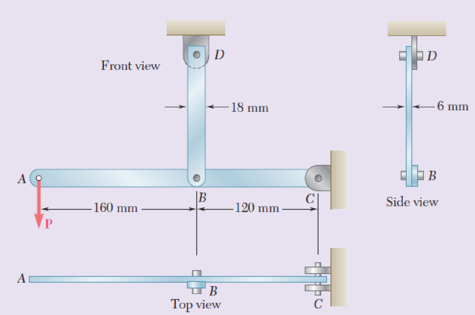
In the steel structure shown, a 6-mm-diameter pin is used at C and 10-mm-diameter pins are used at B and D. The ultimate shearing stress is 150 MPa at all connections, and the ultimate normal stress is 400 MPa in link BD. Knowing that a factor of safety of 3.0 is desired, determine the largest load P that can be applied at A. Note that link BD is not reinforced around the pin holes.
Fig. P1.66
The largest load P that can be applied at A.
Answer to Problem 66RP
The largest load P that can be applied at A is
Explanation of Solution
Given information:
The diameter of the pin at C is
The diameter of the pin at B and D is
The ultimate normal stress
The ultimate normal stress
The factor of safety is 3.0.
Calculation:
Sketch the free body diagram of ABC as shown in Figure 1.
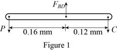
Refer to Figure 1.
Taking moment about C.
Taking moment about B
Find the area of tension on net section of link BD using the relation:
Here, t is the thickness of the section,
Substitute
Find the force in member BD on net section of link BD using the relation:
Here,
Modify Equation (4).
Substitute
Find the area of shear in pins BD using the relation:
Substitute
Find the force in member BD shear in pins BD using the relation:
Here,
Modify Equation (7).
Substitute
Select the smaller value of
Find the value of P as follows:
Substitute
Find the shear in pin at C using the relation:
Substitute
Find the value of C shear in pins C using the relation:
Here,
Modify Equation (10).
Substitute
Find the largest load P such that be applied at A.
Substitute
Select the smaller value of P.
Thus, the largest load P such that be applied at A is
Want to see more full solutions like this?
Chapter 1 Solutions
Mechanics of Materials, 7th Edition


- In the structure shown, an 8-mm diameter pin is used at A, and 12-mm diameter pins are used at B and D. Knowing that the ultimate shearing stress is 100 MPa at all connections and that the ultimate normal stress is 250 MPa in each of the two links joining B and D, determine the allowable load P if an overall factor ofsafety of 3.0 is desired.arrow_forward15. In the steel structure shown, a 6-mm-diamter pin is used at C and 10-mm-diameter pins are used at B and D. The ultimate shearing stress is 150 MPa at all connections, and the ultimate normal stress is 400 MPa in link BD. Knowing that a factor of safety is 3.0 is desired, determine the largest load P that can be applied at A. Note that link BD is not reinforced around the pin holes. Front view 18 mm 6 mm 120 mm- Side view 160 mm Top viewarrow_forward1.55 In the structure shown, an 8-mm-diameter pin is used at A, and 12-mm-diameter pins are used at Band D. Knowing that the ulti- mate shearing stress is 100 MPa at all connections and that the ultimate normal stress is 250 MPa in each of the two links joining B and D. determine the allowable load P if an overall factor of safety of 3.0 is desired. Top siew 12 20 12 mm Front view Side view Fig. P1.55arrow_forward
- 250 mm 400 mm 1.53 Each of the two vertical links CF connecting the two horizontal members AD and EG has a 10 x 40-mm uniform rectangular cross section and is made of a steel with an ultimate strength in tension of 400 MPa, while each of the pins at C and F has a 20-mm diameter and are made of a steel with an ultimate strength in shear of 150 MPa. Determine the overall factor of safety for the links CF and the pins connecting them to the horizontal members. A 250 mm D E F 24 kNarrow_forwardIn the structure shown, an 8-mm-diameter pin is used at A and 12 mmdiameter pins are used at B and D. Knowing that the ultimate shearingstress is 100 MPa at all connections and the ultimate normal stress is 250 MPa in each of the two links joining B and D, determine the allowable load P if an overall factor of safety of 3.0 is desired.arrow_forward1.55 In the structure shown, an 8-mm-diameter pin is used at A, and 12-mm-diameter pins are used at B and D. Knowing that the ulti- mate shearing stress is 100 MPa at all connections and that the ultimate normal stress is 250 MPa in each of the two links joining B and D, determine the allowable load P if an overall factor of safety of 3.0 is desired. Тоp view 200 mm +180 mm - 12 mm 8 mm A В C A 20 mm P 8 mm 8 mm - DO 12 mm - Front view Side view Fig. P1.55arrow_forward
- Each of the two vertical links CF connecting the two horizontal members AD and EG has a 10x40-mm uniform rectangular cross section and is made of a steel with an ultimate strength in tension of 400 MPa,while each of the pins at C and F has a 20-mm diameter and is made of a steel with an ultimate strength in shear of 150 MPa. Determine the overall factor of safety for the links CF and the pins connecting them to the horizontal members.arrow_forwardAn annular washer distributes the load P applied to a steel rod to a timber support. The rod's diameter is 22 mm, and the washer's inner diameter is 25 mm, which is larger than the hole's permissible outer diameter. Knowing that the axial normal stress in the steel rod is 35 MPa and the average bearing stress between the washer and the timber must not exceed 5 MPa, examine the smallest allowed outer diameter, d, of the washer. %3D %3D +22 mm P Figure 4arrow_forwardLink AB is to be made of a steel for which the ultimate normal stress is 450 MPa. Determine the cross-sectional area for AB for which the factor of safety will be 3.50. Assume that the link will be adequately reinforced around the pins at A and B.arrow_forward
- Two links BF are made of steel with a 450-MPa ultimate normal stress and has a 6x12–mm uniform rectangular cross section. Links BF are connected to members ABD and CDEF by 8-mm diameter pins; ABD and CDEF are connected together by a 10-mm diameter pin; CDEF is connected to the support by a 10-mm diameter pin; all of the pins are made of steel with a 170 MPa ultimate shearing stress. Knowing that a factor of safety of 3 is desired, determine the largest load P that may be appliedarrow_forward1. A lever ABC is pinned at C and attached to a 12-mm diameter control cable AD. a. If the allowable tensile stress in the control cable is 140 MPa, what is the maximum safe value of the load P applied as shown in the diagram? b. What is then the shearing stress developed in the 20-mm diameter pin support at C? c. What is the bearing stress between the pin and the 25-mm thick support plates at C?arrow_forwardPROBLEM NO. 2 For the frame shown, a 4998-N load is acting on member ABD at D. If the allowable material shear stress for is 49 MPa, determine the required diameter (rounded off to the nearest 2.5 mm) of the pins at C and D. Pin C and pin D are subjected to double shear and single shear, respectively. If the thickness of member BC is 12 mm and that of member DE is 16 mm, determine the maximum bearing stress at C. 4998-N 1.00 m 1.59 m 45° 0 O B A 1.59 m 1.58 marrow_forward
 Elements Of ElectromagneticsMechanical EngineeringISBN:9780190698614Author:Sadiku, Matthew N. O.Publisher:Oxford University Press
 Mechanics of Materials (10th Edition)Mechanical EngineeringISBN:9780134319650Author:Russell C. HibbelerPublisher:PEARSON
 Thermodynamics: An Engineering ApproachMechanical EngineeringISBN:9781259822674Author:Yunus A. Cengel Dr., Michael A. BolesPublisher:McGraw-Hill Education
 Control Systems EngineeringMechanical EngineeringISBN:9781118170519Author:Norman S. NisePublisher:WILEY
 Mechanics of Materials (MindTap Course List)Mechanical EngineeringISBN:9781337093347Author:Barry J. Goodno, James M. GerePublisher:Cengage Learning
 Engineering Mechanics: StaticsMechanical EngineeringISBN:9781118807330Author:James L. Meriam, L. G. Kraige, J. N. BoltonPublisher:WILEY