
Videos
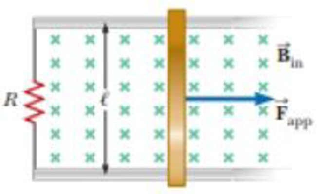
A metal rod of mass m slides without friction along two parallel horizontal rails, separated by a distance ℓ and connected by a resistor R, as shown in Figure P30.13. A uniform vertical magnetic field of magnitude B is applied perpendicular to the plane of the paper. The applied force shown in the figure acts only for a moment, to give the rod a speed v. In terms of m, ℓ, R, B, and v, find the distance the rod will then slide as it coasts to a stop.
Figure P30.13

Trending nowThis is a popular solution!

Chapter 30 Solutions
Physics for Scientists and Engineers with Modern Physics
Additional Science Textbook Solutions
College Physics
Life in the Universe (4th Edition)
Physics of Everyday Phenomena
Conceptual Physics: The High School Physics Program
Physics for Scientists and Engineers, Technology Update (No access codes included)
Tutorials in Introductory Physics


- A metal rod of mass m slides without friction along two parallel horizontal rails, separated by a distance and connected by a resistor R, as shown in Figure P30.13. A uniform vertical magnetic field of magnitude B is applied perpendicular to the plane of the paper. The applied force shown in the figure acts only for a moment, to give the rod a speed v. In terms of m, , R, B, and v, find the distance the rod will then slide as it coasts to a stop. Figure P30.13arrow_forwardA wire is bent in the form of a square loop with sides of length L (Fig. P30.24). If a steady current I flows in the loop, determine the magnitude of the magnetic field at point P in the center of the square. FIGURE P30.24arrow_forwardIn Figure P30.38, the rolling axle, 1.50 m long, is pushed along horizontal rails at a constant speed v = 3.00 m/s. A resistor R = 0.400 is connected to the rails at points a and b, directly opposite each other. The wheels make good electrical contact with the rails, so the axle, rails, and R form a closed-loop circuit. The only significant resistance in the circuit is R. A uniform magnetic field B = 0.080 0 T is vertically downward. (a) Find the induced current I in the resistor. (b) What horizontal force F is required to keep the axle rolling at constant speed? (c) Which end of the resistor, a or b, is at the higher electric potential? (d) What If? After the axle rolls past the resistor, does the current in R reverse direction? Explain your answer. Figure P30.38arrow_forward
- Two infinitely long current-carrying wires run parallel in the xy plane and are each a distance d = 11.0 cm from the y axis (Fig. P30.83). The current in both wires is I = 5.00 A in the negative y direction. a. Draw a sketch of the magnetic field pattern in the xz plane due to the two wires. What is the magnitude of the magnetic field due to the two wires b. at the origin and c. as a function of z along the z axis, at x = y = 0? FIGURE P30.83arrow_forwardFor both sketches in Figure P30.56, there is a 3.54-A current, a magnetic field strength B 0.650 T. and the angle is 32.0. Find the magnetic force per unit length (magnitude and direction) exerted on the current-carrying conductor in both cases.arrow_forwardA metal rod of mass m slides without friction along two parallel horizontal rails, separated by a distance l and connected by a resistor R, as shown in Figure P23.15. A uniform vertical magnetic field of magnitude B is applied perpendicular to the plane of the paper. The applied force shown in the figure acts only for a moment, to give die rod a speed v. In terms of m, l, R, B, and v, find the distance the rod will then slide as it coasts to a stop.arrow_forward
- Figure P30.10 shows a circular current-carrying wire. Using the coordinate system indicated (with the z axis out of the page), state the direction of the magnetic field at points A and B.arrow_forwardA conducting rod of length = 35.0 cm is free to slide on two parallel conducting bars as shown in Figure P30.35. Two resistors R1 = 2.00 and R2 = 5.00 are connected across the ends of the bars to form a loop. A constant magnetic field B = 2.50 T is directed perpendicularly into the page. An external agent pulls the rod to the left with a constant speed of v = 8.00 m/s. Find (a) the currents in both resistors, (b) the total power delivered to the resistance of the circuit, and (c) the magnitude of the applied force that is needed to move the rod with this constant velocity. Figure P30.35arrow_forwardThe triangular loop of wire shown in Figure P30.62 carries a current of 0.125 A, and a uniform magnetic field of 0.250 T points toward the right. Determine the force on each segment of the wire (indicate magnitude and direction) and the net force on the triangular loop.arrow_forward
- Why is the following situation impossible? A conducting rectangular loop of mass M = 0.100 kg, resistance R = 1.00 , and dimensions w = 50.0 cm by = 90.0 cm is held with its lower edge just above a region with a uniform magnetic field of magnitude B = 1.00 T as shown in Figure P30.34. The loop is released from rest. Just as the top edge of the loop reaches the region containing the field, the loop moves with a speed 4.00 m/s. Figure P30.34arrow_forwardA magnetic field directed into the page changes with time according to B = 0.030 0t2 + 1.40, where B is in teslas and t is in seconds. The field has a circular cross section of radius R = 2.50 cm (see Fig. P23.28). When t = 3.00 s and r2 = 0.020 0 m, what are (a) the magnitude and (b) the direction of the electric field at point P2?arrow_forwardA toroid has a major radius R and a minor radius r and is tightly wound with N turns of wire on a hollow cardboard torus. Figure P31.6 shows half of this toroid, allowing us to see its cross section. If R r, the magnetic field in the region enclosed by the wire is essentially the same as the magnetic field of a solenoid that has been bent into a large circle of radius R. Modeling the field as the uniform field of a long solenoid, show that the inductance of such a toroid is approximately L=120N2r2R Figure P31.6arrow_forward
 Physics for Scientists and EngineersPhysicsISBN:9781337553278Author:Raymond A. Serway, John W. JewettPublisher:Cengage Learning
 Physics for Scientists and Engineers with Modern ...PhysicsISBN:9781337553292Author:Raymond A. Serway, John W. JewettPublisher:Cengage Learning
 Principles of Physics: A Calculus-Based TextPhysicsISBN:9781133104261Author:Raymond A. Serway, John W. JewettPublisher:Cengage Learning
 Physics for Scientists and Engineers: Foundations...PhysicsISBN:9781133939146Author:Katz, Debora M.Publisher:Cengage Learning
 Physics for Scientists and Engineers, Technology ...PhysicsISBN:9781305116399Author:Raymond A. Serway, John W. JewettPublisher:Cengage Learning