
Applied Statics and Strength of Materials (6th Edition)
6th Edition
ISBN: 9780133840544
Author: George F. Limbrunner, Craig D'Allaird, Leonard Spiegel
Publisher: PEARSON
expand_more
expand_more
format_list_bulleted
Concept explainers
Videos
Textbook Question
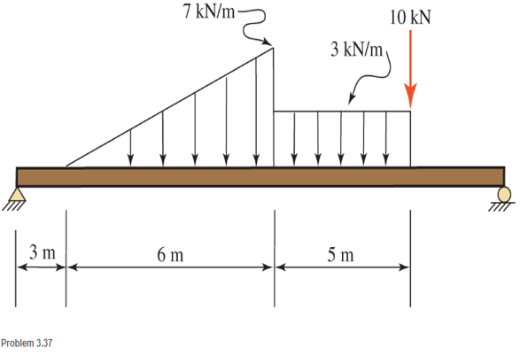
Chapter 3, Problem 3.37P
Determine the magnitude and location of the resultant for the load system shown.
Expert Solution & Answer

Learn your wayIncludes step-by-step video

schedule07:45
Students have asked these similar questions
Problem 6 (Optional, extra 6 points)
150 mm
150 mm
120 mm
80 mm
60 mm
PROBLEM 18.103
A 2.5 kg homogeneous disk of radius 80 mm rotates with an
angular velocity ₁ with respect to arm ABC, which is welded
to a shaft DCE rotating as shown at the constant rate
w212 rad/s. Friction in the bearing at A causes ₁ to
decrease at the rate of 15 rad/s². Determine the dynamic
reactions at D and E at a time when ₁ has decreased to
50 rad/s.
Answer:
5=-22.01 +26.8} N
E=-21.2-5.20Ĵ N
Problem 1.
Two uniform rods AB and CE, each of weight 3 lb and length 2 ft, are welded to each other at their
midpoints. Knowing that this assembly has an angular velocity of constant magnitude c = 12 rad/s,
determine:
(1). the magnitude and direction of the angular momentum HD of the assembly about D.
(2). the dynamic reactions (ignore mg) at the bearings at A and B.
9 in.
3 in.
03
9 in.
3 in.
Answers: HD = 0.162 i +0.184 j slug-ft²/s
HG = 2.21 k
Ay =-1.1 lb; Az = 0; By = 1.1 lb; B₂ = 0.
Problem 5 (Optional, extra 6 points)
A 6-lb homogeneous disk of radius 3 in. spins as shown at the constant rate w₁ = 60 rad/s. The disk
is supported by the fork-ended rod AB, which is welded to the vertical shaft CBD. The system is
at rest when a couple Mo= (0.25ft-lb)j is applied to the shaft for 2 s and then removed. Determine
the dynamic reactions at C and D before and after the couple has been removed at 2 s.
4 in.
C
B
Mo
5 in
4 in.
Note: 2 rotating around CD induced by Mo is NOT
constant before Mo is removed.
and ₂ (two
unknowns) are related by the equation: ₂ =0+ w₂t
3 in.
Partial Answer (after Mo has been removed):
C-7.81+7.43k lb
D -7.81 7.43 lb
Chapter 3 Solutions
Applied Statics and Strength of Materials (6th Edition)
Ch. 3 - through 3.3 Determine the magnitude, direction,...Ch. 3 - Determine the magnitude, direction, and sense of...Ch. 3 - Determine the magnitude, direction, and sense of...Ch. 3 - Solve Problem 3.1 through 3.3 using the method of...Ch. 3 - Solve Problem 3.1 through 3.3 using the method of...Ch. 3 - through 3.6 Solve Problem 3.1 through 3.3 using...Ch. 3 - The 150-lb force shown is the resultant of two...Ch. 3 - Find the resultant force P exerted on the tree.Ch. 3 - Find the resultant force R exerted on the pole.Ch. 3 - Calculate the resultant force on the screw eye....
Ch. 3 - Determine the resultant of the coplanar concurrent...Ch. 3 - Use the parallelogram law to find the following...Ch. 3 - Prob. 3.13PCh. 3 - Determine the resultant of the coplanar concurrent...Ch. 3 - The resultant of the concurrent force system shown...Ch. 3 - Three force of 900 lb, 1000 lb, and 600 lb are...Ch. 3 - The four forces shown hade parallel lines of...Ch. 3 - Three coplanar concurrent forces act as shown. a....Ch. 3 - Four coplanar concurrent forces act as shown a....Ch. 3 - Determine the resultant of the four forces of...Ch. 3 - For the concrete wall and footing shown: a....Ch. 3 - Calculate the moment of the 550-lb force about...Ch. 3 - In Problem 3.22 , calculate the moment about point...Ch. 3 - Compute the moment about point A for the linkage...Ch. 3 - Compute the moment of the force F about point A...Ch. 3 - Determine the magnitude of the resultant of the...Ch. 3 - Determine the magnitude of the resultant of the...Ch. 3 - Determine the magnitude of the resultant of the...Ch. 3 - Determine the magnitude of the resultant of the...Ch. 3 - Determine the resultant and its location for the...Ch. 3 - Compute the magnitude, sense, and location of the...Ch. 3 - Compute the magnitude, sense, and location of the...Ch. 3 - Compute the magnitude and location of the...Ch. 3 - Determine the magnitude and location of the...Ch. 3 - Fresh water is impounded behind a dam to a height...Ch. 3 - Determine the magnitude and location of the...Ch. 3 - Determine the magnitude and location of the...Ch. 3 - Compute the magnitude and direction of the...Ch. 3 - Compute the magnitude and direction of the...Ch. 3 - Compute the magnitude and direction of the...Ch. 3 - A body is subjected to the following three...Ch. 3 - Determine the magnitude, direction, and sense of...Ch. 3 - Determine the magnitude, direction, and sense of...Ch. 3 - Determine the resultant of the load system shown....Ch. 3 - For the concrete structure shown, determine the...Ch. 3 - For the following computer problems, any...Ch. 3 - For the following computer problems, any...Ch. 3 - For the following computer problems, any...Ch. 3 - 3.49 Determine the magnitude, direction, and sense...Ch. 3 - The resultant and one-component force of a...Ch. 3 - The resultant force of a concurrent force system...Ch. 3 - Determine the magnitudes of forces P1 and P2 such...Ch. 3 - The resultant force of a concurrent force system...Ch. 3 - A hockey puck is acted on simultaneously by two...Ch. 3 - Determine the resultant force for each of the...Ch. 3 - Determine the resultant force for each of the...Ch. 3 - The resultant of the three concurrent forces shown...Ch. 3 - The transmission tower shown is subjected to a...Ch. 3 - A gravity-type masonry dam, as shown, depends on...Ch. 3 - The transfomer (as shown) must be lifted...Ch. 3 - Refer to the diagram for Problem 3.60 /. Assume...Ch. 3 - The plastic barrel tent anchor of Problem 2.11...Ch. 3 - Calculate the moment of the forces shown with...Ch. 3 - Determine the magnitude and location of the...Ch. 3 - Determine the moment (about point A) of the appied...Ch. 3 - The lift force on the wing of an aircraft is...Ch. 3 - A beam is subjected to distributed loads as shown....Ch. 3 - For the concrete gravity wall shown, determine the...Ch. 3 - Fresh water is impounded to a height of 8 ft...Ch. 3 - Plank, 2 in. by 10 in. in cross section and 5 ft...Ch. 3 - a. Compute the moment (about point A) of the...Ch. 3 - Determine the resultant of the three forces acting...Ch. 3 - a. Calculate the moments about points A and B due...Ch. 3 - Determine the magnitude of F1 and F2 shown such...Ch. 3 - Calculate the magnitude, direction, and sense of...
Additional Engineering Textbook Solutions
Find more solutions based on key concepts
1. Read the problem statement. 2. Formulate the algorithm using pseudocode and top-down, stepwise refinement. 3...
Java How to Program, Early Objects (11th Edition) (Deitel: How to Program)
Big data Big data describes datasets with huge volumes that are beyond the ability of typical database manageme...
Management Information Systems: Managing The Digital Firm (16th Edition)
A(n) _____ is a set of well-defined steps for performing a task or solving a problem.
Starting Out With Visual Basic (8th Edition)
Find the errors in the following code: 1. // Warning! This code contains ERRORS! if (x = = 1); y = 2; else if (...
Starting Out with Java: From Control Structures through Objects (7th Edition) (What's New in Computer Science)
Fill in the blanks in each of the following statements: A relation that has no partial functional dependencies ...
Modern Database Management
Write a Vole program that places 0s in all the memory cells from address 0xA0 through 0xC0 but is small enough ...
Computer Science: An Overview (13th Edition) (What's New in Computer Science)
Knowledge Booster


Learn more about
Need a deep-dive on the concept behind this application? Look no further. Learn more about this topic, mechanical-engineering and related others by exploring similar questions and additional content below.Similar questions
- Problem 4. A homogeneous disk with radius and mass m is mounted on an axle OG with length L and a negligible mass. The axle is pivoted at the fixed-point O, and the disk is constrained to roll on a horizontal surface. The disk rotates counterclockwise at the constant rate o₁ about the axle. (mg must be included into your calculation) (a). Calculate the linear velocity of G and indicate it on the figure. (b). Calculate ₂ (constant), which is the angular velocity of the axle OG around the vertical axis. (c). Calculate the linear acceleration ā of G and indicate it on the figure. (d). Determine the force (assumed vertical) exerted by the floor on the disk (e). Determine the reaction at the pivot O. 1 Answers: N = mg +mr(r/L)² @² |j mr w IIG C R L i+ 2L =arrow_forwardProblem 2. The homogeneous disk of weight W = 6 lb rotates at the constant rate co₁ = 16 rad/s with respect to arm ABC, which is welded to a shaft DCE rotating at the constant rate 2 = 8 rad/s. Assume the rod weight is negligible compared to the disk. Determine the dynamic reactions at D and E (ignore mg). Answers: D=-7.12ĵ+4.47k lb r-8 in. 9 in. B D E=-1.822+4.47 lb 9 in. E 12 in. 12 in. xarrow_forwardProblem 3. Each of the right angle rods has a mass of 120 g and is welded to the shaft, which rotates at a steady speed of 3600 rpm. Ignore the weight of the shaft AB. Find the bearing dynamic reaction at A due to the dynamic imbalance of the shaft. (ignore mgs) 100 N A 100 100 100 100 100 (Dimensions in millimeters) Answer: A=-8521-426j N Barrow_forward
- Thermodynamics. Need help solving this. Step by step with unitsarrow_forwardQuiz/An eccentrically loaded bracket is welded to the support as shown in Figure below. The load is static. The weld size for weld w1 is h1 = 4mm, for w2 h2=6mm, and for w3 is h3 -6.5 mm. Determine the safety factor (S.f) for the welds. F=29 kN. Use an AWS Electrode type (E100xx). 163 mm 133 mm 140 mm w3 wiarrow_forwardE W X FO FB F10 F11 F12 Home Q: Consider the square of Figure below.The left face is maintained at 100°C and the top face at 500°C, while the other two faces are exposed to an environment at1 00°C, h=10 W/m². C and k=10 W/m.°C. The block is 1 m square. Compute the temperature of the various nodes as indicated in Figure below and the heat flows at the boundaries. T= 500°C Alt Explain to me in detail how to calculate the matrix in the Casio calculator type (fx-991ES plus) T= 100°C 1 2 4 7 1 m- 3 1 m 5 6 T= 100°C 8 9arrow_forward
- Which of the following sequences converge and which diverge? 1) a₁ = 2+(0.1)" 1-2n 2) a = 1+2n 1/n 3 16) a = n In n 17) an = n 1/n 1-5n4 3) an = n² +8n³ 18) an = √4" n n² -2n+1 n! 20) a = 4) an = 106 5) n-1 a₁ =1+(-1)" n+1 a-(+) (1-4) 6) = 7) a = 2n (-1)"+1 2n-1 21) an = n -A" 1/(Inn) 3n+1 22) a = 3n-1 1/n x" 23) a = , x>0 2n+1 3" x 6" 24) a = 2™" xn! 2n 8) a = n+1 πT 1 9) a„ = sin +- 2 n sin n 10) an = n 25) a = tanh(n) 26) a = 2n-1 27) a = tan(n) 1 -sin n n 11) a = 2" 28) an == " 1 + 2" In(n+1) 12) a = n (In n) 200 29) a = n 13) a = 8/n 14) a 1+ =(1+²)" 15) an 7 n = 10n 30) an-√√n²-n 1"1 31) adx nixarrow_forwardA steel alloy contains 95.7 wt% Fe, 4.0 wt% W, and 0.3 wt% C.arrow_forwardb. A horizontal cantilever of effective length 3a, carries two concentrated loads W at a distance a from the fixed end and W' at a distance a from the free end. Obtain a formula for the maximum deflection due to this loading using Mohr's method. If the cantilever is 250 mm by 150mm steel I beam, 3 m long having a second moment of area I as 8500 cm4, determine W and W'to give a maximum deflection of 6 mm when the maximum stress due to bending is 90 Mpa. Take Young's modulus of material E as 185 Gpa.arrow_forward
- Which of the following sequences converge and which diverge? 1/n 1) a₁ = 2+(0.1)" 3 16) a = n 1-2n 2) a = In n 1+2n 17) an = 1/n n 1-5n4 3) an = n² +8n³ 18) an = √4" n n! n² -2n+1 20) a = 4) an = 106 5) n-1 a₁ =1+(-1)" n+1 a-(+) (1-4) 6) = 7) a = 2n (-1)"+1 2n-1 21) an = n -A" 1/(Inn) 3n+1 22) a = 3n-1 1/n x" 23) a = , x>0 2n+1 3" x 6" 24) a = 2™" xn! 2n 8) a = n+1 πT 1 9) a„ = sin +- 2 n sin n 10) an = n 25) a = tanh(n) 26) a = 2n-1 27) a = tan(n) 1 -sin n n 11) a = 2" 28) an == " 1 + 2" In(n+1) 12) a = n (In n) 200 29) a = n 13) a = 8/n 14) a 1+ =(1+²)" 15) an 7 n = 10n 30) an-√√n²-n 1"1 31) adx nixarrow_forwardCalculate the angle of incidence of beam radiation on a collector located at (Latitude 17.40S) on June 15 at 1030hrs solar time. The collector is tilted at an angle of 200, with a surface azimuth angle of 150.arrow_forwardMechanical engineering, please don't use chatgpt. Strict warningarrow_forward
arrow_back_ios
SEE MORE QUESTIONS
arrow_forward_ios
Recommended textbooks for you
 International Edition---engineering Mechanics: St...Mechanical EngineeringISBN:9781305501607Author:Andrew Pytel And Jaan KiusalaasPublisher:CENGAGE L
International Edition---engineering Mechanics: St...
Mechanical Engineering
ISBN:9781305501607
Author:Andrew Pytel And Jaan Kiusalaas
Publisher:CENGAGE L
Types Of loads - Engineering Mechanics | Abhishek Explained; Author: Prime Course;https://www.youtube.com/watch?v=4JVoL9wb5yM;License: Standard YouTube License, CC-BY