
Applied Statics and Strength of Materials (6th Edition)
6th Edition
ISBN: 9780133840544
Author: George F. Limbrunner, Craig D'Allaird, Leonard Spiegel
Publisher: PEARSON
expand_more
expand_more
format_list_bulleted
Concept explainers
Videos
Textbook Question
thumb_up100%
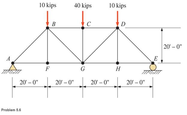
Chapter 5, Problem 5.6P
Calculate the forces in all members of the trusses shown, using the method of joints.
Expert Solution & Answer

Learn your wayIncludes step-by-step video

schedule04:05
Students have asked these similar questions
Correct answer is written below. Detailed and complete solution with fbd only. I will upvote, thank you. Expert solution pls
Correct answer is written below. Detailed and complete solution with fbd only. I will upvote, thank you.
Correct answer is written below. Detailed and complete solution with fbd only. I will upvote, thank you.
Chapter 5 Solutions
Applied Statics and Strength of Materials (6th Edition)
Ch. 5 - through 5.7 Calculate the forces in all members of...Ch. 5 - Calculate the forces in all members of the trusses...Ch. 5 - Calculate the forces in all members of the trusses...Ch. 5 - Calculate the forces in all members of the trusses...Ch. 5 - Calculate the forces in all members of the trusses...Ch. 5 - Calculate the forces in all members of the trusses...Ch. 5 - Calculate the forces in all members of the trusses...Ch. 5 - Determine the forces in members CD, DH, and HI for...Ch. 5 - Determine the forces in members BC, BE, and FE for...Ch. 5 - Determine the forces in members BC, CH, and CG in...
Ch. 5 - For the Howe roof truss shown, determine the...Ch. 5 - Determine the forces in members DE, CE, and BC in...Ch. 5 - Calculate the forces in members BC, BG, and FG for...Ch. 5 - Determine the forces in members CD, BD, BE, and CB...Ch. 5 - A pin-connected A-frame supports a load, as shown....Ch. 5 - Determine the pin reactions at pins A, B, and C in...Ch. 5 - Calculate the pin reactions at each of the pins in...Ch. 5 - A bracket is pin connected at points A, B, and D...Ch. 5 - A pin-connected frame is loaded, as shown....Ch. 5 - The cylinder shown has a mass of 500 kg. Determine...Ch. 5 - A simple frame is pin connected at points A, B,...Ch. 5 - Using the method of sections, determine the forces...Ch. 5 - Using the method of sections, determine the forces...Ch. 5 - through 5.31 Calculate the forces in all members...Ch. 5 - Calculate the forces in all members of the trusses...Ch. 5 - Calculate the forces in all members of the trusses...Ch. 5 - Calculate the forces in all members of the trusses...Ch. 5 - Calculate the forces in all members of the trusses...Ch. 5 - Calculate the forces in all members of the trusses...Ch. 5 - Calculate the forces in all members of the trusses...Ch. 5 - Calculate the forces in all members of the trusses...Ch. 5 - For Problems 5.32 through 5.38, calculate the...Ch. 5 - For Problem 5.32 through 5.38, Calculate the...Ch. 5 - For Problems 5.32 through 5.38, calculate the...Ch. 5 - For Problems 5.32 through 5.38, calculate the...Ch. 5 - For Problem 5.32 through 5.38 , Calculate the...Ch. 5 - For Problems 5.32 through 5.38, calculate the...Ch. 5 - For Problems 5.32 through 5.38, calculate the...Ch. 5 - A pin-connected crane framework is loaded and...Ch. 5 - Calculate the pin reactions at pins A, B, and D in...Ch. 5 - Determine the pin reactions at pins A, B, and C in...Ch. 5 - The wall bracket shown is pin-connected at points...Ch. 5 - Calculate the pin reactions at each of the pins in...Ch. 5 - The A-frame shown is pin-connected at A,B,C, and...Ch. 5 - The tongs shown are used to grip an object. For an...Ch. 5 - A toggle joint is a mechanism by which a...Ch. 5 - In the toggle joint of Problem 5.46 , assume that...Ch. 5 -
Additional Engineering Textbook Solutions
Find more solutions based on key concepts
What is the importance of modeling in engineering? How are the mathematical models for engineering processes pr...
HEAT+MASS TRANSFER:FUND.+APPL.
The beam is made of steel having an allowable normal stress of allow = 150 MPa and an allowable shear stress of...
Mechanics of Materials (10th Edition)
Write an IfThen statement that assigns 0 to intX when intY is equal to 20.
Starting Out With Visual Basic (8th Edition)
Determine the force in each member of the truss, and state if the members are in tension or compression Set = ...
INTERNATIONAL EDITION---Engineering Mechanics: Statics, 14th edition (SI unit)
In an inheritance relationship, the _____ is the general class. a. subclass b. superclass c. slave class d. chi...
Starting Out with Programming Logic and Design (5th Edition) (What's New in Computer Science)
ICA 10-6
The worksheet provided was designed to calculate the total pressure felt by an object submerged in a f...
Thinking Like an Engineer: An Active Learning Approach (4th Edition)
Knowledge Booster


Learn more about
Need a deep-dive on the concept behind this application? Look no further. Learn more about this topic, mechanical-engineering and related others by exploring similar questions and additional content below.Similar questions
- Correct answer is written below. Detailed and complete solution only with fbd. I will upvote, thank you.arrow_forwardCorrect answer is written below. Detailed and complete solution only. I will upvote, thank you.arrow_forwardCorrect answer is written below. Detailed and complete solution with fbd only. I will upvote, thank you.arrow_forward
- Correct answer is written below. Detailed and complete solution only. I will upvote, thank you.arrow_forwardCorrect answer is written below. Detailed and complete solution with fbd only. I will upvote, thank you.arrow_forwardCorrect answer is written below. Detailed and complete solution only. I will upvote, thank you.arrow_forward
- Correct answer is written below. Detailed and complete solution only. I will upvote, thank you.arrow_forwardCorrect answer is written below. Detailed and complete solution only. I will upvote, thank you.arrow_forwardCorrect answer is written below. Detailed and complete solution with fbd only. I will upvote, thank you. Prefferably handwritten solution pleasearrow_forward
- Correct answer is written below. Detailed and complete solution with fbd only. I will upvote, thank you. Prefferably handwritten solution pleasearrow_forwardCorrect answer is written below. Detailed and complete solution only. I will upvote, thank you.arrow_forwardCorrect answer is written below. Detailed and complete solution with fbd only. I will upvote, thank you. Prefferably handwritten solution pleasearrow_forward
arrow_back_ios
SEE MORE QUESTIONS
arrow_forward_ios
Recommended textbooks for you
 International Edition---engineering Mechanics: St...Mechanical EngineeringISBN:9781305501607Author:Andrew Pytel And Jaan KiusalaasPublisher:CENGAGE L
International Edition---engineering Mechanics: St...
Mechanical Engineering
ISBN:9781305501607
Author:Andrew Pytel And Jaan Kiusalaas
Publisher:CENGAGE L
Engineering Basics - Statics & Forces in Equilibrium; Author: Solid Solutions - Professional Design Solutions;https://www.youtube.com/watch?v=dQBvQ2hJZFg;License: Standard YouTube License, CC-BY