
Concept explainers
Videos
A cylindrical cast-iron casting has an axial bole extending partway through the casting, as shown. Locate the center of gravity of the casting.
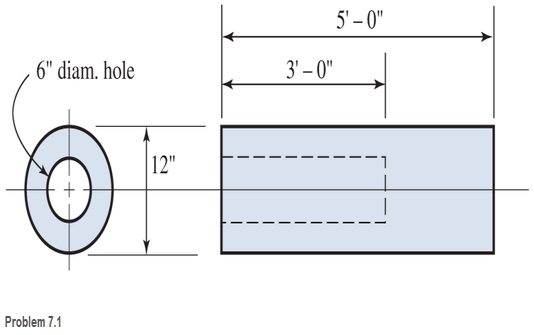
The location of the center of gravity of the casting.
Answer to Problem 7.1P
Explanation of Solution
Given information:
Given a cylindrical cast iron casting having an axial hole extending pathway through the casting.
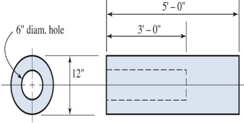
The centroid of a body can be found with two axes taken into consideration. As, the given figure is symmetrical about X-axis, so the centroid must lie on the X-axis. Now, by calculating the weight of the given member with reference to densities taken from U S Customary codes for typical average properties of some common materials. Thereby, in reference to the codes the weight of cast iron is taken as
Calculation:
Let W1the weight of the whole cylinder and W2 the weight of the empty space considering its density same as that of the cast iron.
Now we have,
Conclusion:
Therefore, the location of center of gravity of the casting is
Want to see more full solutions like this?
Chapter 7 Solutions
Applied Statics and Strength of Materials (6th Edition)
Additional Engineering Textbook Solutions
Starting Out with Java: From Control Structures through Objects (7th Edition) (What's New in Computer Science)
Elementary Surveying: An Introduction To Geomatics (15th Edition)
Modern Database Management
Introduction To Programming Using Visual Basic (11th Edition)
Starting Out With Visual Basic (8th Edition)
Starting Out with Programming Logic and Design (5th Edition) (What's New in Computer Science)


- Determine by direct integration the moment of inertia of theshaded area of figure with respect to the y axis shownarrow_forwardConsider the feedback controlled blending system shown below, which is designed to keep theoutlet concentration constant despite potential variations in the stream 1 composition. The density of all streamsis 920 kg/m3. At the nominal steady state, the flow rates of streams 1 and 2 are 950 and 425 kg/min,respectively, the liquid level in the tank is 1.3 m, the incoming mass fractions are x1 = 0.27, x2 = 0.54. Noticethe overflow line, indicating that the liquid level remains constant (i.e. any change in total inlet flow ratetranslates immediately to the same change in the outlet flow rate). You may assume the stream 1 flowrate andthe stream 2 composition are both constant. Use minutes as the time unit throughout this problem. Identify any controlled variable(s) (CVs), manipulated variable(s) (MVs),and disturbance variable(s) (DVs) in this problem. For each, explain how you know that’show it is classified.CVs: ___________, MVs: _____________, DVs: ______________ b) Draw a block diagram…arrow_forwardA heat transfer experiment is conducted on two identical spheres which are initially at the same temperature. The spheres are cooled by placing them in a channel. The fluid velocity in the channel is non-uniform, having a profile as shown. Which sphere cools off more rapidly? Explain. V 1arrow_forward
- My ID# 016948724 last 2 ID# 24 Last 3 ID# 724 Please help to find the correct answer for this problem using my ID# first write le line of action and then help me to find the forces {fx= , fy= mz= and for the last find the moment of inertial about the show x and y axes please show how to solve step by steparrow_forwardMy ID# 016948724 last 2 ID# 24 Last 3 ID# 724 Please help to find the correct answer for this problem using my ID# first write le line of action and then help me to find the forces and the tension {fx= , fy= mz=arrow_forwardMy ID# 016948724 last 2 ID# 24 Last 3 ID# 724 Please help to find the correct answer for this problem using my ID# first write le line of action and then help me to find the forces {fx= , fy= mz=arrow_forward
- my ID is 016948724 Last 2 ID# 24 Last 3 ID# 724 please help me to solve this problem step by step show me how to solve first wirte the line actions and then find the forces {fx=, fy=, mz= and for the last step find the support reactions and find forcesarrow_forwardUppgift 1 (9p) 3 m 3 m 3 m 3 m H G F 3 m ↑ Dy D B AAY 30° 8 kN Ay Fackverket i figuren ovan är belastat med en punktlast. Bestäm normalkraften i stängerna BC, BG och FG.arrow_forwardThe cardiovascular countercurrent heat exchnager mechanism is to warm venous blood from 28 degrees C to 35 degrees C at a mass flow rate of 2 g/s. The artery inflow temp is 37 degrees C at a mass flow rate of 5 g/s. The average diameter of the vein is 5 cm and the overall heat transfer coefficient is 125 W/m^2*K. Determine the overall blood vessel length needed too warm the venous blood to 35 degrees C if the specific heat of both arterial and venous blood is constant and equal to 3475 J/kg*K.arrow_forward
- The forces Qy=12 kNQy=12kN and Qz=16 kNQz=16kN act on the profile at the shear center C. Calculate: a) Shear flow at point B (2 points)b) Shear stress at point D (3 points)arrow_forwardConsider the feedback controlled blending system shown below, which is designed to keep theoutlet concentration constant despite potential variations in the stream 1 composition. The density of all streamsis 920 kg/m3. At the nominal steady state, the flow rates of streams 1 and 2 are 950 and 425 kg/min,respectively, the liquid level in the tank is 1.3 m, the incoming mass fractions are x1 = 0.27, x2 = 0.54. Noticethe overflow line, indicating that the liquid level remains constant (i.e. any change in total inlet flow ratetranslates immediately to the same change in the outlet flow rate). You may assume the stream 1 flowrate andthe stream 2 composition are both constant. Use minutes as the time unit throughout this problem. d) Derive the first order process and disturbance transfer functions;Gp= Kp/(tou*s+1) and Gd=Kd/(tou*s+1) and calculate and list the values and units of the parameters. e) Using the given information, write the general forms of Gm, GIP, and Gv below(in terms of…arrow_forwarda) Briefly explain what ratio control is. Give an example of a common chemical engineering situation in whichratio control would be useful and for that example state exactly how ratio control works (what would bemeasured, what is set, and how the controller logic works).b) Briefly explain what cascade control is. Give an example of a common chemical engineering situation inwhich cascade control would be useful and for that example state exactly how cascade control works (whatwould be measured, what is set, and how the controller logic works).arrow_forward
 International Edition---engineering Mechanics: St...Mechanical EngineeringISBN:9781305501607Author:Andrew Pytel And Jaan KiusalaasPublisher:CENGAGE L