
Introductory Circuit Analysis (13th Edition)
13th Edition
ISBN: 9780133923605
Author: Robert L. Boylestad
Publisher: PEARSON
expand_more
expand_more
format_list_bulleted
Related questions
Question
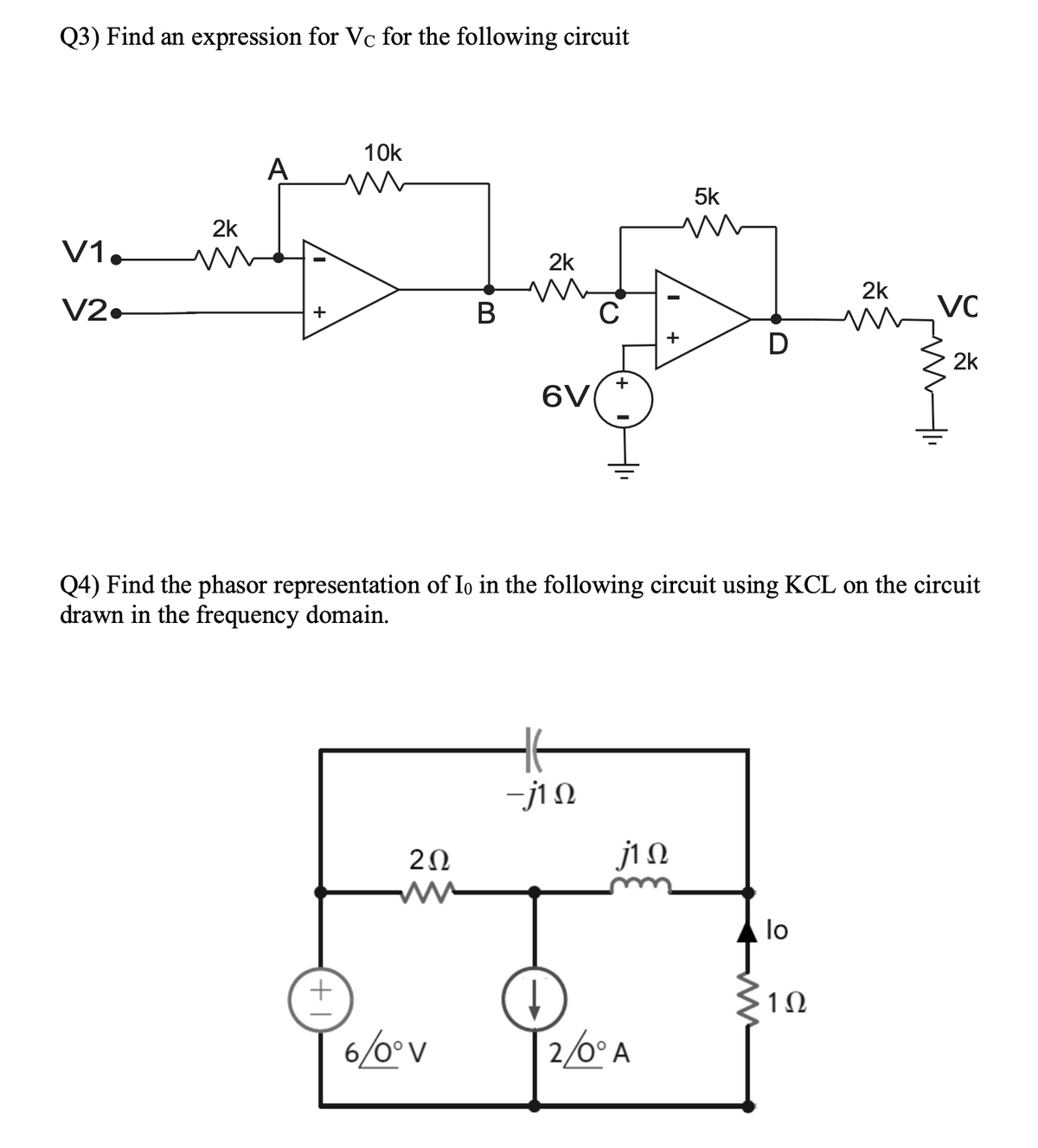

Transcribed Image Text:Q3) Find an expression for Vc for the following circuit
V1.
V2•
2k
A
10k
w
5k
w
2k
2k
+
B
C
w
VC
+
D
2k
+
6V
Q4) Find the phasor representation of Io in the following circuit using KCL on the circuit
drawn in the frequency domain.
| +
202
ww
-j10
j10
lo
1Ω
6/0°V
2/0° A
Expert Solution
This question has been solved!
Explore an expertly crafted, step-by-step solution for a thorough understanding of key concepts.

Step by stepSolved in 2 steps with 1 images

Knowledge Booster

Similar questions
- Power in Extreme Frequency Limits. You and your team have been assigned to find a power supply for the circuit in the drawing. which can be used to supply a dc voltage at 15.0 V, or a high frequency ac signal with a root-mean-square (rms) voltage of 15.0 V. The components in the circuit have the following values: R=4.600, C= 20 nF, and L = 22 mH. Your task is to estimate the peak wattage (i.e.. power) required of the power supply for (a) the dc and (b) the high frequency signals. Conceptual Example 5 will provide insight into this problem. (a) Number (b) Number 24.4 196 R ww Units W Units W C HH elle L Rarrow_forwardIN A SERIES RLC CIRCUIT DRIVEN BY SINUSOIDAL INPUT SIGNAL, THE PHASE BETWEEN THE CURRENT AND THE INPUT VOLTAGE IS PLOTTED IN THE NEXT GRAPH. When the frequency f = 60 kHz the phase (in radians) between the voltage on the capacitor and the voltage on the inductor is about: 1.6 1.2 0.8 0.4 -0.4 -0.8 -1.2 -1.6 1 10 100 1000 Frequency (f), kHz O a. zero O b. -1.57 O c. 0.003 O d. 1.57 O e. 3.14 Phase (0 ), radarrow_forwardFind the natural frequency for Vc for the following circuit given the following parameters. Solve for the differential equation symbolically so that you can use the same result in the next question. Otherwise you will have to repeat the process with new numbers. Also be wary of the given units. C = 1mF, L = 3mH, R₁ = 42, R₂ = 9 and R3 = 100 12v R₁ t=0 * R₂ R3arrow_forward
- I need help with this problem and an explanation of the solution for the image described below. (Introduction to Signals and Systems)arrow_forwardIf a DC source (frequency equal to zero) was used instead, what should be the ideal resistor and inductor voltages in a series RL circuit? Support through your answer by providing a computation. If a DC source (frequency equal to zero) was used instead, what should be the ideal resistor and capacitor voltages in a series RC circuit? Support through your answer by providing a computation.arrow_forwardA nonperiodic composite signal has a bandwidth of 170 kHz, with a middle frequency of 120 kHz and a peak amplitude of 20 V. The two extreme frequencies have an amplitude of 10 V. 1. The lowest frequency is KHz. 2. The highest frequency is KHz. Draw the frequency domain of the signal. (You don't need to submit the curve to the Canvas.)arrow_forward
- An 50 resistor, a 5 mH inductor, and a 1.25 μF capacitor are connected in series. The series-connected elements are energized by a sinusoidal voltage source whose voltage is 600 cos(8000t+ 20°)V. Part A Determine the impedances of the elements in the frequency-domain equivalent circuit. Express your answers in ohms to three significant figures separated by commas. Enter your answers in rectangular form. ZL, ZC, ZR= Submit Part B ΠΫΠΙ ΑΣΦ Ig= Request Answer ΑΣΦ | 11 Ivec Reference the current in the direction of the voltage rise across the source, and find the phasor current. Express answer in amperes to three significant figures. Enter your answer using angle notation. Express argument in degrees. vec ? ? A Ωarrow_forwardAn 50 resistor, a 5 mH inductor, and a 1.25 μF capacitor are connected in series. The series-connected elements are energized by a sinusoidal voltage source whose voltage is 600 cos(8000t+20°) V. Part A Determine the impedances of the elements in the frequency-domain equivalent circuit. Express your answers in ohms to three significant figures separated by commas. Enter your answers in rectangular form. IVE ΑΣΦ ZL. ZC, ZR= 40,100,50 vec You have already submitted this answer. Enter a new answer. No credit lost. Try again. Submit Previous Answers Request Answer ? Ωarrow_forwarda) Given the sinusoidal voltage source in a linear o i) The amplitude of the voltage 6 UTM 5 U ii) The angular frequency TM & UTM 5 UTM 8 UTM UTM & UTM iv) The value of V, at 1 = 3 ms 5 UTM 5 UTM 8 [ D UTM 8 UTM 8 UTM UTM UTM & UTarrow_forward
- Determine which waveform in each of the following pairs is lagging: a.) cos4t, sin4t;b.)cos(4t-80), cos (4t)c.) cos (4t+ 80)d.) -sin5t, cos(5t+2)e.) sin 5t+ cos 5t, cos (5t-45) Can anyone help me with this exercise and also please show me the complete solution so that I can study and understand it well. thank you.arrow_forwardb) Two circuits connected in series which voltage drop across at each circuit can be expressed in time TTM domain as V1 (t) =5 sin (3147) V and V2 (1) =15 sin (314t - 30°) V. Sketch the waveforms of these voltages to illustrate peak values and phase relationships. UTM 5 UTM UTM TM S UTM UTM TM 5 UTM 8 UTMarrow_forward1. Suppose that MATLAB is used to plot a sinusoidal signal. The following MATLAB code generates the signal and makes the plot. Draw a sketch of the plot that will be done by MATLAB. Determine the amplitude (A), phase ($), and period of the sinusoid and label the period on your plot. dt = 0.001; tt = = .05 dt : .15; Fo = 8; Z sqrt (2) * (1-j); xx = real( Z*exp( 2j*pi*Fo*tt ) ); plot tt, XX ), grid title( 'SECTION of a SINUSOID' ), xlabel('TIME (sec)')arrow_forward
arrow_back_ios
SEE MORE QUESTIONS
arrow_forward_ios
Recommended textbooks for you
- Introductory Circuit Analysis (13th Edition)Electrical EngineeringISBN:9780133923605Author:Robert L. BoylestadPublisher:PEARSON
 Delmar's Standard Textbook Of ElectricityElectrical EngineeringISBN:9781337900348Author:Stephen L. HermanPublisher:Cengage Learning
 Programmable Logic ControllersElectrical EngineeringISBN:9780073373843Author:Frank D. PetruzellaPublisher:McGraw-Hill Education
  Fundamentals of Electric CircuitsElectrical EngineeringISBN:9780078028229Author:Charles K Alexander, Matthew SadikuPublisher:McGraw-Hill Education
 Electric Circuits. (11th Edition)Electrical EngineeringISBN:9780134746968Author:James W. Nilsson, Susan RiedelPublisher:PEARSON
 Engineering ElectromagneticsElectrical EngineeringISBN:9780078028151Author:Hayt, William H. (william Hart), Jr, BUCK, John A.Publisher:Mcgraw-hill Education,
Introductory Circuit Analysis (13th Edition)
Electrical Engineering
ISBN:9780133923605
Author:Robert L. Boylestad
Publisher:PEARSON
Delmar's Standard Textbook Of Electricity
Electrical Engineering
ISBN:9781337900348
Author:Stephen L. Herman
Publisher:Cengage Learning
Programmable Logic Controllers
Electrical Engineering
ISBN:9780073373843
Author:Frank D. Petruzella
Publisher:McGraw-Hill Education
Fundamentals of Electric Circuits
Electrical Engineering
ISBN:9780078028229
Author:Charles K Alexander, Matthew Sadiku
Publisher:McGraw-Hill Education
Electric Circuits. (11th Edition)
Electrical Engineering
ISBN:9780134746968
Author:James W. Nilsson, Susan Riedel
Publisher:PEARSON
Engineering Electromagnetics
Electrical Engineering
ISBN:9780078028151
Author:Hayt, William H. (william Hart), Jr, BUCK, John A.
Publisher:Mcgraw-hill Education,