
Introductory Circuit Analysis (13th Edition)
13th Edition
ISBN: 9780133923605
Author: Robert L. Boylestad
Publisher: PEARSON
expand_more
expand_more
format_list_bulleted
Related questions
Question
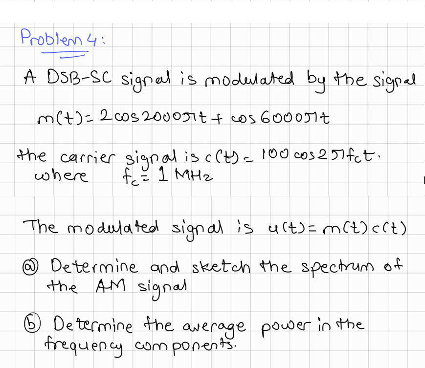

Transcribed Image Text:Problem 4:
A DSB-SC signal is modulated by the signal
m(t)=2cos 2000πt + cos 6000πt
the carrier signal is c(t) = 100 cos 257fct.
fc = 1 MHz
where
The modulated signal is u(t) = m (t)<(t)
Determine and sketch the spectrum of
the AM signal
⑤ Determine the average power in the
frequency components.
Expert Solution
This question has been solved!
Explore an expertly crafted, step-by-step solution for a thorough understanding of key concepts.

Step by stepSolved in 2 steps with 2 images

Knowledge Booster

Similar questions
- answer all questions pleasearrow_forward05 A DSB-SC AM signal is modulated by the signal 71 (?) == Bcos2000nt + cos6000nt The modulated signal is u(:) -- 100m (:)cos2nf,t 1-Determine and sketch the spectrum of the AM signal. 2-Determine the average power in the frequency components. where f = 1 MH:arrow_forwardEXERCISES: 1. An AM signal has the following characteristics; the carrier frequency is 150MHz; the modulating signal frequency is 3KHz; the carrier voltage is 60V, where the modulating signal is 20V. Find the peak voltage of lower side frequency. 2. Determine whether the given equation of AM signal represents an overmodulation or not. VAM (t)=5sin (2л630,000t) +7cos (21625,000t) +7cos (21635,000t)arrow_forward
- Starting from the general expression of the frequency modulated wave, find out the expression of narrow band FM (NBFM).arrow_forwardAn FM radio broadcast used a modulator with a frequency deviation sensitivity of 5KHz/V, a 2Vp – 10 kHz modulating signal, and a 10Vp – 88MHz carrier Signal , determine. Use this Bessel table below to solve this problem. (a) Actual minimum bandwidth from the Bessel function table in kHzarrow_forwardX. The frequency spectrum of an AM signal is shown below: 1V 5.5V 1V 59kHz 51kHz a) if the modulating signal is a sine wave, write the equation of the modulating signal b) if the carrier signal is a cosine wave, write the equation of the carrier signal c) calculate the current of the AM signal flowing through a 300-ohm loadarrow_forward
- Answer all question.arrow_forwardAn FM signal has a maximum frequency deviation of 1500h and a modulating frequency of 500h, its total power is 6500w, applied to a resistive load of 1ohm, the carrier frequency is 400Mhz. Determine the sensitivity of the modulator, and the magnitude spectrumarrow_forward1) Find the energy in the signal x[n] = 2(0.12)", n20. %3D 2) Given a periodic signal of x[n] = 2cos(2 m/4) whose period is N = 4. Find its average value and signal power. 3) Given a periodic signal of x[n] = 9e24 whose period is N=4. Find its signal power. 4) Sketch each signal and its even and odd parts. (1) x[n] = 8(0.5)' u[n] (ii) x[n]= u[n] (iii) x[n]=1+ u[n] (iv) x[n] = u[n]-u[n – 4] (v) (vi) x[n]= {6,4,2, 2}arrow_forward
- plz ans itarrow_forwardOpe X. The frequency spectrum of an AM signal is shown below: 5.5V 1V 1V 52kHz 58kHz a) if the modulating signal is a sine wave, write the equation of the modulating signal b) if the carrier signal is a cosine wave, write the equation of the carrier signal c) calculate the current of the AM signal flowing through a 300-ohm loadarrow_forwardThe equation for finding the period, when frequency is kniwn is . .arrow_forward
arrow_back_ios
SEE MORE QUESTIONS
arrow_forward_ios
Recommended textbooks for you
- Introductory Circuit Analysis (13th Edition)Electrical EngineeringISBN:9780133923605Author:Robert L. BoylestadPublisher:PEARSON
 Delmar's Standard Textbook Of ElectricityElectrical EngineeringISBN:9781337900348Author:Stephen L. HermanPublisher:Cengage Learning
 Programmable Logic ControllersElectrical EngineeringISBN:9780073373843Author:Frank D. PetruzellaPublisher:McGraw-Hill Education
  Fundamentals of Electric CircuitsElectrical EngineeringISBN:9780078028229Author:Charles K Alexander, Matthew SadikuPublisher:McGraw-Hill Education
 Electric Circuits. (11th Edition)Electrical EngineeringISBN:9780134746968Author:James W. Nilsson, Susan RiedelPublisher:PEARSON
 Engineering ElectromagneticsElectrical EngineeringISBN:9780078028151Author:Hayt, William H. (william Hart), Jr, BUCK, John A.Publisher:Mcgraw-hill Education,
Introductory Circuit Analysis (13th Edition)
Electrical Engineering
ISBN:9780133923605
Author:Robert L. Boylestad
Publisher:PEARSON
Delmar's Standard Textbook Of Electricity
Electrical Engineering
ISBN:9781337900348
Author:Stephen L. Herman
Publisher:Cengage Learning
Programmable Logic Controllers
Electrical Engineering
ISBN:9780073373843
Author:Frank D. Petruzella
Publisher:McGraw-Hill Education
Fundamentals of Electric Circuits
Electrical Engineering
ISBN:9780078028229
Author:Charles K Alexander, Matthew Sadiku
Publisher:McGraw-Hill Education
Electric Circuits. (11th Edition)
Electrical Engineering
ISBN:9780134746968
Author:James W. Nilsson, Susan Riedel
Publisher:PEARSON
Engineering Electromagnetics
Electrical Engineering
ISBN:9780078028151
Author:Hayt, William H. (william Hart), Jr, BUCK, John A.
Publisher:Mcgraw-hill Education,