Introductory Circuit Analysis (13th Edition)
13th Edition
ISBN: 9780133923605
Author: Robert L. Boylestad
Publisher: PEARSON
expand_more
expand_more
format_list_bulleted
Question

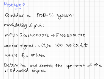
Transcribed Image Text:Problem 2:
Consider a
DSB-SC system:
modulating signal:
m(t)= 2 cos4000 πt +5 cos 6000 Jit
carrier signal: c(t) = 100 cos 257fct
where f= 50kHz.
Determine and sketch the spectrum of the
modulated signal.
Expert Solution
This question has been solved!
Explore an expertly crafted, step-by-step solution for a thorough understanding of key concepts.
Step by stepSolved in 2 steps with 3 images

Knowledge Booster
Similar questions
- Q2: A modulating signal is used to modulate a carrier signal(AM modulation). Let Pr . Pc. PSB. PuSB. PLSB and u are the total power, carrier power, side band power, upper side band power, lower side band power and modulation index respectively. Prove the following: a. Pc = Pr () c. Pusn = Pisn =) Pr m2 b. Psn = Pr %3D 2+m2 LSB 2+m? (2+m2arrow_forwardA 1500 KHz carrier with amplitude of 50 V is amplitude modulated by 2 –KHz sine wave tone with a peak voltage of 15 V. Determine the modulation index, percent modulation, the upper and lower sideband frequencies, bandwidth of the wave, and write the AM equation.arrow_forwardAn AM transmitter at 27 MHz develops 10W of carrier power into a 50-ohm load. It is modulated by 2-kHz sine wave between 20% and 90% modulation. Determine maximum and minimum waveform voltage of the AM signal at 20%. Ans: Vmax=37.94V and Vmin=25.3Varrow_forward
- Modify this circuit to extend the upper frequency limit to greater than 15 MHz. You may change the topology (i.e. configuration), but not the power supply voltage or collector bias current. The circuit voltage gain must be 46dB +/- 1 dB. Provide simulation results to show AC frequency responses of both circuits on the same plot, and annotate the 3dB upper frequency limit on both traces. Use typical ẞ values from the data sheet for the simulation. You may assume that 1% resistors are available in values below 100. The circuit must adhere to Standard Bias techniques. V4 Rser=0 SINE(0 0.02 10k) AC 1 VCC ୯ V2 +15V Cin1 1μ -VCC VCC R4 Rc1 147k 7k Q3 2N3904 R7 R6 9.09 20.5k Ce1 Re1 1.00k 10p Outarrow_forwardA baseband signal has the spectrum sketched in the first image added below. The baseband signal modulates a 98 kHz carrier sine wave. Using frequency and amplitude labelling similar to that in Figure 2, sketch the spectrum of the modulated signal using a template added in image 2, for the following modulations: i-AM with the amplitude of the carrier wave being 20 V ii-DSBSC iii-SSB – the lower sideband iv-SSB – the upper sidebandarrow_forward.arrow_forward
- A carrier signal is amplitude modulated by a sinewave. The resulting AM waveform is shown below. 3.5V- 1V- a) What is the amplitude of the carrier signal? b) c) To achieve 75 percent modulation, what amplitude of the modulating signal is needed? d) Calculate the effective voltage of the AM signal What is the modulation index?arrow_forwardQuestion 3 a) For a single-frequency sine wave modulating signal of 3 kHz with a carrier frequency of 36 MHz, what is the spacing between sidebands? b) A carrier of 49 MHz is frequency-modulated by a 1.5-kHz square wave. The modulation index is 0.25. Sketch the spectrum of the resulting signal. (Assume only harmonics less than the sixth are passed by the system.)arrow_forwardQ2: Draw the output PSK waveform for the digital data: Input signal Carrier Input Q: What is the main benefit of measuring the scattering parameters of RF network?arrow_forward
- If the maximum frequency deviation is 25kHz and modulating signal frequency is 12kHz. 6c. Is this FM treated as narrow band or wide band?arrow_forwardQuestion 4. Select the statement that best describes the PM wave.a. Carrier phase angle changes represent the PM modulated signal, however, unlike FM and AM modulatedcarriers, it is not always easy to see these phase changes in the plot.b. The FM signal accurately represents the message.c. Although PM and FM techniques are classified as angular modulation techniques, they cannot be usedinterchangeably (i.e., modulated with FM and demodulated with PM, and visa versa).d. All statements are correct.arrow_forward2. Determine the peak phase deviation and modulation index for a PM modulator with a deviation sensitivity K = 2.5 rad/V and a modulating signal v(t) = 2 cos (212000t). %3Darrow_forward
arrow_back_ios
SEE MORE QUESTIONS
arrow_forward_ios
Recommended textbooks for you
 Introductory Circuit Analysis (13th Edition)Electrical EngineeringISBN:9780133923605Author:Robert L. BoylestadPublisher:PEARSON
 Delmar's Standard Textbook Of ElectricityElectrical EngineeringISBN:9781337900348Author:Stephen L. HermanPublisher:Cengage Learning
 Programmable Logic ControllersElectrical EngineeringISBN:9780073373843Author:Frank D. PetruzellaPublisher:McGraw-Hill Education
 Fundamentals of Electric CircuitsElectrical EngineeringISBN:9780078028229Author:Charles K Alexander, Matthew SadikuPublisher:McGraw-Hill Education
 Electric Circuits. (11th Edition)Electrical EngineeringISBN:9780134746968Author:James W. Nilsson, Susan RiedelPublisher:PEARSON
 Engineering ElectromagneticsElectrical EngineeringISBN:9780078028151Author:Hayt, William H. (william Hart), Jr, BUCK, John A.Publisher:Mcgraw-hill Education,

Introductory Circuit Analysis (13th Edition)
Electrical Engineering
ISBN:9780133923605
Author:Robert L. Boylestad
Publisher:PEARSON

Delmar's Standard Textbook Of Electricity
Electrical Engineering
ISBN:9781337900348
Author:Stephen L. Herman
Publisher:Cengage Learning

Programmable Logic Controllers
Electrical Engineering
ISBN:9780073373843
Author:Frank D. Petruzella
Publisher:McGraw-Hill Education

Fundamentals of Electric Circuits
Electrical Engineering
ISBN:9780078028229
Author:Charles K Alexander, Matthew Sadiku
Publisher:McGraw-Hill Education

Electric Circuits. (11th Edition)
Electrical Engineering
ISBN:9780134746968
Author:James W. Nilsson, Susan Riedel
Publisher:PEARSON

Engineering Electromagnetics
Electrical Engineering
ISBN:9780078028151
Author:Hayt, William H. (william Hart), Jr, BUCK, John A.
Publisher:Mcgraw-hill Education,