
Introductory Circuit Analysis (13th Edition)
13th Edition
ISBN: 9780133923605
Author: Robert L. Boylestad
Publisher: PEARSON
expand_more
expand_more
format_list_bulleted
Related questions
Question
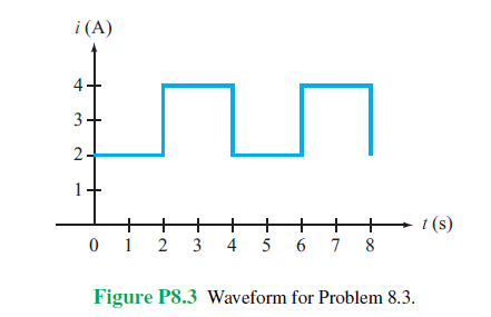
Determine (a) the average and (b) rms values of the periodic
current waveform shown in Fig. P8.3.

Transcribed Image Text:i (A)
+
3+
2-
1
+
+
+
+
+
t(s)
0 1
2
3
4 5 6 7 8
Figure P8.3 Waveform for Problem 8.3.
Expert Solution
This question has been solved!
Explore an expertly crafted, step-by-step solution for a thorough understanding of key concepts.

Step by stepSolved in 2 steps with 2 images

Knowledge Booster

Similar questions
- 7. In DC analysis all capacitors are replaced by a short circuit equivalent and in AC as an open circuit. Select one:TrueFalse 8. En el análisis AC del BJT todas las fuentes de cd se hacen igual a cero y las reemplaza una conexión de cortocircuito a tierra. Seleccione una: Verdadero Falso 9. The superposition theorem is applicable to the analysis and design of the dc and ac components of a BJT network, allowing the analysis of the system's dc and ac responses to be separated. Select one:TrueFalse 10. An equivalent model is a combination of appropriately selected circuit elements that accurately simulates the real behavior of a semiconductor device in any operating condition. Select one:TrueFalsearrow_forward8. Let us consider the following circuit: Vin R Vin (a) Find an expression for Vout in terms of Vin, d, R, C, and R. (b) For this part, assume R = R and R*C = 1s. Also take Vin to be a triangle wave of amplitude 1V and period 1s. Draw a plot of Vin and Vout- (The triangle wave should start from zero and rise linearly to its maximum of 1V, which it reaches at t = 0.5s; it should then decrease linearly back to OV, which it reaches at t = 1s.) (c) Consider changing the circuit to: R R Vi-W Cg RE www How would this change your results to (a) and (b)? (Hint: what are in and i, for the op-amp? This isn't hard!) (d) Consider the following circuit: + Find Vout as a function of V₁, R, RF, C, and RE RE ww Rg Ce Vout RE www Vout -Voutarrow_forwardDetermine which waveform in each of the following pairs is lagging: a.) cos4t, sin4t;b.)cos(4t-80), cos (4t)c.) cos (4t+ 80)d.) -sin5t, cos(5t+2)e.) sin 5t+ cos 5t, cos (5t-45) Can anyone help me with this exercise and also please show me the complete solution so that I can study and understand it well. thank you.arrow_forward
- Match the differential expression to its units. ✓rdp A V V R2 sin0d0dp R² sin0d0dqdR - ✓ de A. m² B. m3 C. m D. radarrow_forwardb) Two circuits connected in series which voltage drop across at each circuit can be expressed in time TTM domain as V1 (t) =5 sin (3147) V and V2 (1) =15 sin (314t - 30°) V. Sketch the waveforms of these voltages to illustrate peak values and phase relationships. UTM 5 UTM UTM TM S UTM UTM TM 5 UTM 8 UTMarrow_forwardcalculate theoretical time constant of the RL circuit in Figure8.2 for the given range of L (include RF GEN in your calculations). Record your values in Table 8.3.arrow_forward
- A series RLC circuit is excited by a 100 volts 79.6 Hz source. Resistance R is 100 ohms, Inductance L is 1 H and capacitance C is 5 micro farad. Calculate the voltage across C. A. 250+1250 B.-200-1200 C. 50-150 D. -235.21235.2arrow_forwardQ6. Figure Q6 shows a modulated waveform v(t) in microvolts as a function of time t in nanoseconds. 25 50 75 100 125 150 175 200 225 250 50 40 40 30 30 20 20 10 10 -10 -10 -20 -20 -30 -30 -40 -40 -50 -50 250 25 50 75 100 125 150 175 200 225 time/ns Figure Q6: Modulated waveform (a) Describe the modulation scheme. (b) What are the values of the carrier frequency and the modulation frequency? (c) What is the value of the modulation index? (d) What is the transmission efficiency (ratio of modulated to total power) in this example? (e) Sketch the spectrum of this modulated waveform indicating the relative magnitudes of the various spectral components. (f) The modulating wave in this example is substituted with a square wave of 50% duty cycle and of fundamental frequency 1.0 MHz. Sketch the absolute value of the spec- trum of the modulated waveform indicating the frequencies and relative magnitudes of the sideband components. (g) Demodulation of this type of signal is usually accomplished…arrow_forwardHere you have a signals related subject ... Please answer this question fast and give it a simple explanation Thank you!arrow_forward
- 11. For the unity feedback system shown in Figure P8.3, where K (3 – 9) G(s) : (s2 + 4) sketch the root locus and tell for what values of K the system is stable and unstable. [Section: 8.5]arrow_forwardSS Precision 3450 DELL a8ed Task #3: Remember these identities: TC = COS sin A = cos (v-s00 D -v) Convert a sine signal into a cosine signal. Let S3(t) = 5 sin(2n100t) Write s3 (t) signal in cosine form: Convert a cosine signal into a sine signal. Let S4(t) = 10 cos(2n50t) Write s,(t) signal in sine form: 直 0 F1 F2 F4 F5arrow_forwardSolve all parts.arrow_forward
arrow_back_ios
SEE MORE QUESTIONS
arrow_forward_ios
Recommended textbooks for you
- Introductory Circuit Analysis (13th Edition)Electrical EngineeringISBN:9780133923605Author:Robert L. BoylestadPublisher:PEARSON
 Delmar's Standard Textbook Of ElectricityElectrical EngineeringISBN:9781337900348Author:Stephen L. HermanPublisher:Cengage Learning
 Programmable Logic ControllersElectrical EngineeringISBN:9780073373843Author:Frank D. PetruzellaPublisher:McGraw-Hill Education
  Fundamentals of Electric CircuitsElectrical EngineeringISBN:9780078028229Author:Charles K Alexander, Matthew SadikuPublisher:McGraw-Hill Education
 Electric Circuits. (11th Edition)Electrical EngineeringISBN:9780134746968Author:James W. Nilsson, Susan RiedelPublisher:PEARSON
 Engineering ElectromagneticsElectrical EngineeringISBN:9780078028151Author:Hayt, William H. (william Hart), Jr, BUCK, John A.Publisher:Mcgraw-hill Education,
Introductory Circuit Analysis (13th Edition)
Electrical Engineering
ISBN:9780133923605
Author:Robert L. Boylestad
Publisher:PEARSON
Delmar's Standard Textbook Of Electricity
Electrical Engineering
ISBN:9781337900348
Author:Stephen L. Herman
Publisher:Cengage Learning
Programmable Logic Controllers
Electrical Engineering
ISBN:9780073373843
Author:Frank D. Petruzella
Publisher:McGraw-Hill Education
Fundamentals of Electric Circuits
Electrical Engineering
ISBN:9780078028229
Author:Charles K Alexander, Matthew Sadiku
Publisher:McGraw-Hill Education
Electric Circuits. (11th Edition)
Electrical Engineering
ISBN:9780134746968
Author:James W. Nilsson, Susan Riedel
Publisher:PEARSON
Engineering Electromagnetics
Electrical Engineering
ISBN:9780078028151
Author:Hayt, William H. (william Hart), Jr, BUCK, John A.
Publisher:Mcgraw-hill Education,