
Introductory Circuit Analysis (13th Edition)
13th Edition
ISBN: 9780133923605
Author: Robert L. Boylestad
Publisher: PEARSON
expand_more
expand_more
format_list_bulleted
Related questions
Question
use fig 4 to solve the problem
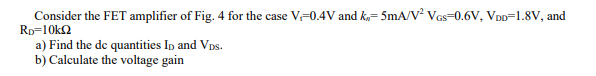

Transcribed Image Text:Consider the FET amplifier of Fig. 4 for the case V-0.4V and k=5mA/V² VGS=0.6V, VDD=1.8V, and
RD=10k
a) Find the de quantities ID and VDs.
b) Calculate the voltage gain

Transcribed Image Text:Vas
Fig. 4
VDD
Rp
obs
Expert Solution
This question has been solved!
Explore an expertly crafted, step-by-step solution for a thorough understanding of key concepts.

Step by stepSolved in 2 steps with 1 images

Knowledge Booster

Similar questions
- 1. The BJT amplifier below is biased with current source I. a. Find the DC voltage at the collector, Vc. b. Find the value of gm. 24 +5 V 8.2 k -0 Vc + # 1=0.5 mAarrow_forwardplease solve, do not use any other resourcesarrow_forward1. Assume that the source voltage for the D-MOSFET in the following figure is measured and found to be 1.6 V. a. Compute lo and Vos- b. If gm = 2000 umho, what is the voltage gain? c. Compute the input resistance of the amplifier. d. Is the D-MOSFET operating in the depletion or the enhancement mode? 100 my pp 1.0 kHz HI C₁ 0.1 µF R₁ 5.1 ΜΩ R₂ 10 ΜΩ +VDD +24 V ① RD 2.7 C3 Rs 330 Ω OV ORI C₂ 33 μFarrow_forward
- 7) Consider the multi-stage amplifier shown below with its corresponding small signal model. Using the provided small Vo Vin signal model, perform small signal analysis to determine expressions the you would need to determine Av Do NOT solve for Av, just provide the expressions that you would need to determine Av. Show your work! Do NOT make any approximations. Vin + Vgs Vin Vcc Rd1 M1 gm 1 Vgs ro1 Vo1 Vo1 Vcc ww ww1. Rd1 Rc2 Q2 Re2 + Vbe rπ2 Vo www. gm2 Vbe Re2 WWW ro2 ww - Vo Rc2arrow_forwardb)The transistor consists of three terminals. The main reason for designing configurations is that it requires four terminals in order to provide the input and the output connections of the circuit for effective amplification. Now in your own words describe how Bipolar Transistors Transistor ( BJT ) various configurations are designed with relating diagrams. In your own estimation evalute which one is most widely used when looking at appreciable output for an amplifier?arrow_forwardFor the BJT amplifier given in Figure, Find the small-signal input resistance Ri. Given: B=100, l=1mA Vcc vi A. infinite B. 25 Ohm C. VT/I Ri D. 2500 Ohm +V I -VEE E. Additional info is required to find. +voarrow_forward
- Vo 7) Consider the multi-stage amplifier shown below with its corresponding small signal model. Using the provided small signal model, perform small signal analysis to determine expressions the you would need to determine Av Vin Do NOT solve for Av, just provide the expressions that you would need to determine Av. Write your answer's and show your work! Do NOT make any approximations. Vin Vcc Rd1 M1 Vo1 Vin 2 quot + Vgs gm1 Vgs ro1 Vo1 Vcc WWW www. Rd1 Rc2 Q2 Re2 Vo + 4 Vbe rл2 gm2 Vbe Re2 ro2 Vo Rc2arrow_forwardQ2: For the circuit shown in figure (2), he=100 for all transistors and 1/hobs = 200k2. Find: a. DC values for Ics, Ici. Vez, Ic7 and Vco. b. Ad, A, and CMRR of the difference amplifier. +15v 10KE 100k 1k 10k Q8 Q3 v1 Q7 25k Q1 Q2 14.3k Q5 Q6 Q9 -15v Figure (2)arrow_forwardConsider the circuit shown below of a common source amplifier with a current mirror bias. Find the following: a. Find kp and kn. b. Find the drain current of M2 given that IBIAS = 2mA and VouT = 2.5V. c. Find the gm and r. of transistor M1. d. Sketch the small signal model of transistor M3 (Hint: Is there any small signal in any terminal of M3? If yes, then where is it? If no, then what happens to the small signal model?). It is given that the NMOS (M1) parameters are H,Con = 3mA/V? , VTH,n = 0.5V and A = 0.02 and the PMOS (M2 and M3) parameters are µ.Cox = 1mA/V? and VTH,p = -0.6V. The PMOS transistor M3 does not have channel length modulation while PMOS transistor M2 has A = 0.02. It is also given that the dimensions of M2 and M3 have equal widths of 5µm and lengths of L2 = 3µm and L3 = 1.5µm, respectively. M1 has length of L1 = 1µm and width of W1 = 2µm. 5V 5V M3 M2 VOUT VIN M1 IBIASarrow_forward
- Please answer in typing format please ASAP for the like please clear the solution Please answer all subpartarrow_forwardplease solve, with few steps as possible and show all formulasarrow_forward6) Consider the amplifier shown below. Assume that the transistors are modeled asfollows: Mla and M1b: Kn1 = 8mA/V?, VTN = 1V, 11 = .05V1 M2 a and M2 b Kn2 = 16MA/V, VTN = 1V, A2 = .01V1 a) Determine Vocm. Show your work! b) Determine the differential voltage gain. Show your work! 6V 6V 1.5K 1.5K 6V Voa Vob Vina Vinb 2m A M1a M1b ww 500 500 M2b M2aarrow_forward
arrow_back_ios
SEE MORE QUESTIONS
arrow_forward_ios
Recommended textbooks for you
- Introductory Circuit Analysis (13th Edition)Electrical EngineeringISBN:9780133923605Author:Robert L. BoylestadPublisher:PEARSON
 Delmar's Standard Textbook Of ElectricityElectrical EngineeringISBN:9781337900348Author:Stephen L. HermanPublisher:Cengage Learning
 Programmable Logic ControllersElectrical EngineeringISBN:9780073373843Author:Frank D. PetruzellaPublisher:McGraw-Hill Education
  Fundamentals of Electric CircuitsElectrical EngineeringISBN:9780078028229Author:Charles K Alexander, Matthew SadikuPublisher:McGraw-Hill Education
 Electric Circuits. (11th Edition)Electrical EngineeringISBN:9780134746968Author:James W. Nilsson, Susan RiedelPublisher:PEARSON
 Engineering ElectromagneticsElectrical EngineeringISBN:9780078028151Author:Hayt, William H. (william Hart), Jr, BUCK, John A.Publisher:Mcgraw-hill Education,
Introductory Circuit Analysis (13th Edition)
Electrical Engineering
ISBN:9780133923605
Author:Robert L. Boylestad
Publisher:PEARSON
Delmar's Standard Textbook Of Electricity
Electrical Engineering
ISBN:9781337900348
Author:Stephen L. Herman
Publisher:Cengage Learning
Programmable Logic Controllers
Electrical Engineering
ISBN:9780073373843
Author:Frank D. Petruzella
Publisher:McGraw-Hill Education
Fundamentals of Electric Circuits
Electrical Engineering
ISBN:9780078028229
Author:Charles K Alexander, Matthew Sadiku
Publisher:McGraw-Hill Education
Electric Circuits. (11th Edition)
Electrical Engineering
ISBN:9780134746968
Author:James W. Nilsson, Susan Riedel
Publisher:PEARSON
Engineering Electromagnetics
Electrical Engineering
ISBN:9780078028151
Author:Hayt, William H. (william Hart), Jr, BUCK, John A.
Publisher:Mcgraw-hill Education,