
Delmar's Standard Textbook Of Electricity
7th Edition
ISBN: 9781337900348
Author: Stephen L. Herman
Publisher: Cengage Learning
expand_more
expand_more
format_list_bulleted
Related questions
Question
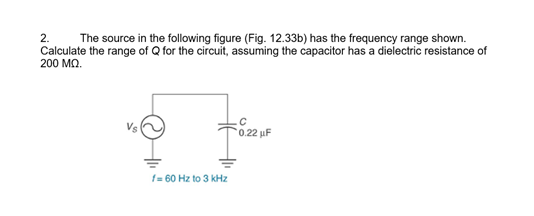

Transcribed Image Text:2.
The source in the following figure (Fig. 12.33b) has the frequency range shown.
Calculate the range of Q for the circuit, assuming the capacitor has a dielectric resistance of
200 MQ.
Vs
f=60 Hz to 3 kHz
0.22 uF
Expert Solution
This question has been solved!
Explore an expertly crafted, step-by-step solution for a thorough understanding of key concepts.

Step by stepSolved in 2 steps with 2 images

Knowledge Booster

Similar questions
- R 1. Measure the internal resistance of the 1mH inductor. Set up the given circuit with R = 270n and L = 1mH. Apply a sinusoidal voltage as input. Adjust V, = 4Vpp and set the frequency as 20kHz. Observe the input voltage and the V, L voltage across the inductor simultaneously using an ocilloscope and plot both signals. Find the phase difference between these signals and comment on the results.arrow_forwardBest choicearrow_forwardb) A capacitor C is connected in series with a 40 O resistor across a supply of frequency 60 Hz. A current of 3A flows and the circuit impedance is 50 N, Calculate: (i) the value of capacitance, C, (ii) the supply voltage, (ii) the phase angle between the supply voltage and current, (iv) the p.d. across the resistor, (v) the p.d. across the capacitor.arrow_forward
- Please answer it only correct.arrow_forwardA 10.0-μF capacitor and a 2.00-H inductor are connected in series with a 60.0-Hz source whose rms output is 100 V. Finda. the rms current in the circuit.b. the voltage drop across the inductor. c. the voltage drop across the capacitor.arrow_forward10 V sine 90 kHz 1 kQ C1 1 nF 2. Using a Square function with 90,000 Hz in your function-generator, a 1000-ohm resistor, and a 1 nano-Farad capacitor, determine the charging time for the capacitor. Show your calculations and show the charging-discharge curve with an oscilloscope in TINKERCAD.arrow_forward
- 1. Is it possible to determine the phase relationship between a power phasor and the corresponding voltage and current phasors? Explain why. 2. What is the phase relationship between the reactive power in an inductor and the reactive power in a capacitor? 3. What are the differences between the active power P, reactive power Q, and apparent power S?arrow_forwardConsider the sinusoidal voltage and current for an inductor. If you are given the phase angle of the voltage, the phase angle of the current will be:a) The same as the voltage phase angleb) 90°more than the voltage phase anglec) 90° less than the voltage phase angled) Dependent on the inductancearrow_forwardA capacitor has a reactance of 80 ohms when connected to a 50 Hz supply. Calculate the value of capacitance.a. 39.79 microfaradb. 39.97 microfaradc. 93.79 microfaradd. 93.97 microfaradKindly provide a CLEAR and COMPLETE solution.arrow_forward
- An AC circuit is composed of a serial connection of: a resistor with resistance 50 0, a coil with inductance 0.3 H and a capacitor with capacitance 15 µF. The circuit is connected to an AC voltage source with amplitude 25 V and frequency 50 Hz. Determine the amplitude of the electric current in the circuit and a phase difference between the voltage and the current. R=50 2 C=15 µF omH L=0.3 H U.-25 V f=50 Hz Hi guys! Here is something you can practice with. Simplify the circuit above. The final answer is RLC circuit the amplitude of the current is approximate: /m = 0.2 A. %3D The phase difference between the voltage and the current is about: p = -67°. %3Darrow_forwardA capacitor C is connected in series with a 400 resistor across a supply of frequency 60 Hz. A current of 3 A flows and the circuit impedance is 500. Calculate: (a) the value of capacitance, C, (b) the supply voltage, (c) the phase angle between the supply voltage and current, (d) the p.d. across the resistor, and (e) the p.d. across the capacitor. Draw the Phasor diagram.arrow_forwardI need an answer in a short timearrow_forward
arrow_back_ios
SEE MORE QUESTIONS
arrow_forward_ios
Recommended textbooks for you
- Delmar's Standard Textbook Of ElectricityElectrical EngineeringISBN:9781337900348Author:Stephen L. HermanPublisher:Cengage Learning
Delmar's Standard Textbook Of Electricity
Electrical Engineering
ISBN:9781337900348
Author:Stephen L. Herman
Publisher:Cengage Learning