
Introductory Circuit Analysis (13th Edition)
13th Edition
ISBN: 9780133923605
Author: Robert L. Boylestad
Publisher: PEARSON
expand_more
expand_more
format_list_bulleted
Related questions
Question
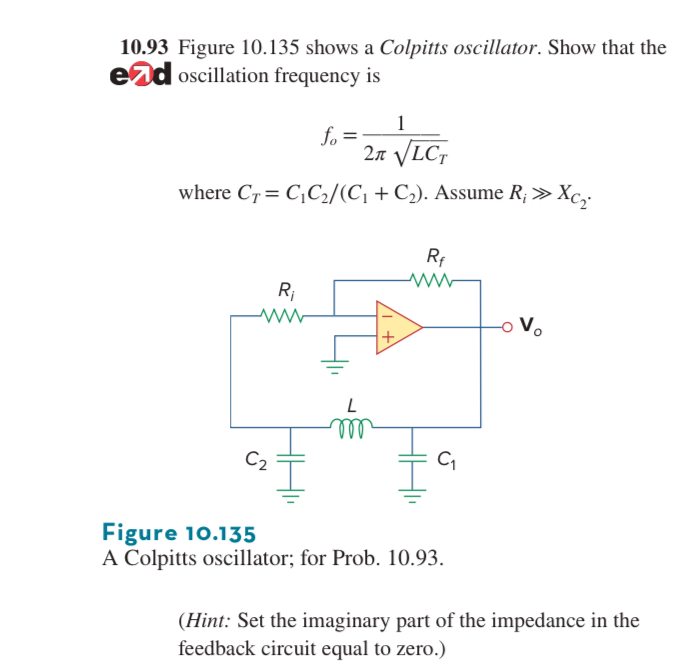

Transcribed Image Text:10.93 Figure 10.135 shows a Colpitts oscillator. Show that the
ed oscillation frequency is
1
fo=
2π √√LCT
where CTC₁C2/(C₁ + C₂). Assume R; >>>
R₁
+
Rf
ww
Vo
L
m
C₂
C₁
5
Xci
Figure 10.135
A Colpitts oscillator; for Prob. 10.93.
(Hint: Set the imaginary part of the impedance in the
feedback circuit equal to zero.)
Expert Solution
This question has been solved!
Explore an expertly crafted, step-by-step solution for a thorough understanding of key concepts.

Step by stepSolved in 2 steps with 1 images

Knowledge Booster

Similar questions
- Topic : Pulse Modulation and Sampling theorem 1.C.)arrow_forward10. SERPSE10 27.4.OP.021. Consider a series RC circuit as in the figure below for which R=4.00 MQ, C= 4.00 uF, and - 34.0 V. DETAILS (a) Find the time constant of the circuit. R (b) What is the maximum charge on the capacitor after the switch is thrown closed? Need Help? Q (c) Find the current in the resistor 10.0 s after the switch is closed. LA Wicht MY NOTES ASK YOUR TEACHEarrow_forwardQ6. Figure Q6 shows a modulated waveform v(t) in microvolts as a function of time t in nanoseconds. 25 50 75 100 125 150 175 200 225 250 50 40 40 30 30 20 20 10 10 -10 -10 -20 -20 -30 -30 -40 -40 -50 -50 250 25 50 75 100 125 150 175 200 225 time/ns Figure Q6: Modulated waveform (a) Describe the modulation scheme. (b) What are the values of the carrier frequency and the modulation frequency? (c) What is the value of the modulation index? (d) What is the transmission efficiency (ratio of modulated to total power) in this example? (e) Sketch the spectrum of this modulated waveform indicating the relative magnitudes of the various spectral components. (f) The modulating wave in this example is substituted with a square wave of 50% duty cycle and of fundamental frequency 1.0 MHz. Sketch the absolute value of the spec- trum of the modulated waveform indicating the frequencies and relative magnitudes of the sideband components. (g) Demodulation of this type of signal is usually accomplished…arrow_forward
- A nonperiodic composite signal has a bandwidth of 170 kHz, with a middle frequency of 120 kHz and a peak amplitude of 20 V. The two extreme frequencies have an amplitude of 10 V. 1. The lowest frequency is KHz. 2. The highest frequency is KHz. Draw the frequency domain of the signal. (You don't need to submit the curve to the Canvas.)arrow_forward16. An RTD has α0 = 0.0035 /oC at T0= 50o C and Resistance R(T0)= 300 Ω . Determine the resistance at 20oC.arrow_forward1. If R1 = 10K, R2 = R3 = 10K, R4 = 5K, Vs = 10V, what is the total current IT. Use the image below: %3D R, R3 2. What is the time constant for a RC circuit with C = 10 µF & R = 500K 3. if the peak-to-peak value of this signal is 10 V, what is the RMS value? use the image below: %3D ? V 1.0 mS-arrow_forward
- Build an AC RLC circuit a) Choose values for voltage, frequency, resistance, capacitance and inductance. b) Calculate the impedance, phase angle and resonant frequency.arrow_forwardIn the following figure, R=9kΩ ad Cf=3nF. Vin(t)=5sin(2pi*10khz*t) draw the output waveform Vin and Vo and derive the expression of the Vo(t) as a function of time & Vo(f) as a function of varying signal frequency.arrow_forwardDesign (only the block diagram) an Armstrong indirect FM modulator to generate an FM carrier with a carrier frequency of 96 MHz and Af = 20 kHz. A narrow-band FM generator with fe = 200 kHz and adjustable Af in the range of 9 to 10 Hz is available. The stock room also has an oscillator with adjustable frequency in the range of 9 to 10 MHz. There is a bandpass filter with any center frequency, and only frequency doublers are available.arrow_forward
arrow_back_ios
SEE MORE QUESTIONS
arrow_forward_ios
Recommended textbooks for you
- Introductory Circuit Analysis (13th Edition)Electrical EngineeringISBN:9780133923605Author:Robert L. BoylestadPublisher:PEARSON
 Delmar's Standard Textbook Of ElectricityElectrical EngineeringISBN:9781337900348Author:Stephen L. HermanPublisher:Cengage Learning
 Programmable Logic ControllersElectrical EngineeringISBN:9780073373843Author:Frank D. PetruzellaPublisher:McGraw-Hill Education
  Fundamentals of Electric CircuitsElectrical EngineeringISBN:9780078028229Author:Charles K Alexander, Matthew SadikuPublisher:McGraw-Hill Education
 Electric Circuits. (11th Edition)Electrical EngineeringISBN:9780134746968Author:James W. Nilsson, Susan RiedelPublisher:PEARSON
 Engineering ElectromagneticsElectrical EngineeringISBN:9780078028151Author:Hayt, William H. (william Hart), Jr, BUCK, John A.Publisher:Mcgraw-hill Education,
Introductory Circuit Analysis (13th Edition)
Electrical Engineering
ISBN:9780133923605
Author:Robert L. Boylestad
Publisher:PEARSON
Delmar's Standard Textbook Of Electricity
Electrical Engineering
ISBN:9781337900348
Author:Stephen L. Herman
Publisher:Cengage Learning
Programmable Logic Controllers
Electrical Engineering
ISBN:9780073373843
Author:Frank D. Petruzella
Publisher:McGraw-Hill Education
Fundamentals of Electric Circuits
Electrical Engineering
ISBN:9780078028229
Author:Charles K Alexander, Matthew Sadiku
Publisher:McGraw-Hill Education
Electric Circuits. (11th Edition)
Electrical Engineering
ISBN:9780134746968
Author:James W. Nilsson, Susan Riedel
Publisher:PEARSON
Engineering Electromagnetics
Electrical Engineering
ISBN:9780078028151
Author:Hayt, William H. (william Hart), Jr, BUCK, John A.
Publisher:Mcgraw-hill Education,