
Elements Of Electromagnetics
7th Edition
ISBN: 9780190698614
Author: Sadiku, Matthew N. O.
Publisher: Oxford University Press
expand_more
expand_more
format_list_bulleted
Related questions
Question
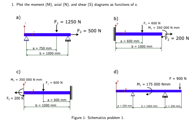

Transcribed Image Text:1. Plot the moment (M), axial (N), and shear (S) diagrams as functions of z.
a)
b)
F₁ = 1250 N
F₁ = 600 N
M₁ = 350 000 N mm
F2 = 500 N
200 N
a = 600 mm
b=1000 mm
a=750 mm
b = 1000 mm
d)
M₁ = 350 000 N mm
F₁ = 600 N
F₂ =200 N
a = 600 mm
b = 1000 mm
M₁ 175 000 Nmm
F = 900 N
a-250 mm
b-1000 mm
-250 mm.
Figure 1: Schematics problem 1.
Expert Solution
This question has been solved!
Explore an expertly crafted, step-by-step solution for a thorough understanding of key concepts.

Step by stepSolved in 2 steps with 4 images

Knowledge Booster

Similar questions
- Why does this guy always provide incorrect solutions. :( I will reportarrow_forward3) A point mass is attached to one end of a beam levered against a spike which acts as the pivot. The point mass weighs 250N and the beam has a uniform mass of 10kg and is 8m long. Parts a and b Part c Fapplied 3 of 6mov 1m 8m Krist 0 = 60° Scale 250 N Scale a. If a scale placed beneath the point mass reads 250N, what is the magnitude and direction for the force at the pivot point? Direction: North, 90° from x-axis Magnitude to k* 250N = 2500 N b. For the same scenario, how far must the pivot point be located relative to the left edge of the beam? (Hint, both the boxes weight and the force from the scale act at the farthest right edge of the beam.) www.acta 0672nos onl c. The pivot is then moved to be 6m from the left edge of the beam which now makes a 60 angle with the floor. How much downward force would be needed at the left-most edge of the beam to reduce the reading on the scale to zero? (Hint: the beam is still in static eq. when the scale reads zero.)arrow_forwardReview Learning Goal: To use the vector cross product to calculate the moment produced by a force, or forces, about a specified point on a member. Part A - Moment due to a force specified by magnitude and endpoints The moment of a force F about the moment axis passing through O and perpendicular to the plane containing O and F can be expressed using the vector cross product, Mo =r x F. In a properly constructed Cartesian coordinate system, the vector cross product can be calculated using a matrix determinant: As shown, a member is fixed at the origin, point O, and has an applied force F, the tension in the rope, applied at the free end, point B. (Figure 1) The force has magnitude F = 180 N and is directed as shown. The dimensions are ¤1 = 0.350 m, x2 = 1.90 m, y1 = 2.30 m, and z1 = 1.20 m. What is the moment about the origin due to the applied force F? i j M =rx F =|rz k Express the individual components of the Cartesian vector to three significant figures, separated by commas. ry F F,…arrow_forward
- L=9m W=5kN/m 360 UB 50.7arrow_forward15 kN/m 50 kN 150 kN m A 3 m E B 6 m 3 m -3 m a) Determine the reactions at supports A (pin) and D (roller). b) Determine the internal loading at x= 3 m (point E) measured from point A. c) Write functions for shear force (V) in terms of x d) Write functions for bending moment (M) in terms of x.arrow_forwardFarrow_forward
- A bar with varying cross section is subjected to various forces as shown below. Compute: a) Stresses in each section b) strain in each section c) total extension of the bar. Take E = 2.1x10⁵ N/mm² 400 mm² P1=10kN A 1000 mm B 800 mm mm² P₂ P3=45KN+ 1500 mm 600 mm² 800 mm → P4-35kNarrow_forward5. Determine the value of the distributed load w and the concentrated loads x, y and z in the load diagram. [x=5.75kN, y=15kN, w= 5kN/m, z=34.25kN] 80 kN-m 5.75 X V (kN) 50N A 5m V (N) M (Nm) B 5 -9.25 6. Determine the value of A, B in the shear force diagram and C in the bending moment diagram. [A =50N; B = -50N; C = 125Nm] 10N/m 10m -5m- C W Z -.x(m) -34.25 50N -x (m) B -x (m)arrow_forwardA composite beam is under external loads as shown below. a) Draw the internal shear force and bending moment diagrams under the graph for the beam. Label the shear force and bending moment with values for each controlling point on the diagrams. b) Find the maximum tensile and compressive stresses. 12 mm 75 kN 40 kN/m 48 mm В 12 mm A 96 mm 1.8 m Cross section 0.9 m (not drawn to scale) 3.6 marrow_forward
- Draw the FBD and show all the forces Calculate force for weight (W) gl=32.174 ft/s^2 Determine summation of forces in Y direction and X direction and set=0 Determine summation of moments with respect to point A and set=0arrow_forwardQUESTION 2 Question 2 A cross-section of a beam is shown in Figure Q2. If the shear force in this section is V = 125 KN, determine the value and the location of the maximum shear stress in the section. In Figure Q2, a = 30 mm and the origin of the coordinate system is at centroid of the cross section. 7 y= Z= A a AY S= 20 4a mm; mm; O Figure Q2 Answer The vertical coordinate (y-coordinate; the y-axis serves as the axis of symmetry of the cross- section.) and horizontal coordinate (z-coordinate) of the location where the maximum shear stress occurs in the section are ← a The vertical distance from the location where the maximum shear stress occurs in the section to the bottom side (AB cross section can be calculated as Distance = mm (units: mm) 3a Second moment of area The second moment of area employed in the equation to calculate maximum shear stress can be calculated as I₂ = a (units: mm²) Shear stress The second moment of area employed in the equation to calculate maximum shear…arrow_forwardA wooden beam is loaded by a distributed load w = 5 N/mm as shown in Figure Q4(a). The cross-section of the beam is shown in Figure Q4(b). Assume that LAB = 1600 mm, LBC = 3400 mm, W=190 mm, Bo = 20 mm, and H = 200 mm, ho=40 mm. Units: use N, mm, MPa as consistent units for all calculations. Decimal points: any decimal points are fine and all the numerical questions have a 10% error tolerance. (a) (b) hol Во H B LAB LBC Cross-section W Figure Q4: (a) A wooden beam is loaded by a distributed load, (b) cross-section of the beam.arrow_forward
arrow_back_ios
SEE MORE QUESTIONS
arrow_forward_ios
Recommended textbooks for you
- Elements Of ElectromagneticsMechanical EngineeringISBN:9780190698614Author:Sadiku, Matthew N. O.Publisher:Oxford University Press
 Mechanics of Materials (10th Edition)Mechanical EngineeringISBN:9780134319650Author:Russell C. HibbelerPublisher:PEARSON
 Thermodynamics: An Engineering ApproachMechanical EngineeringISBN:9781259822674Author:Yunus A. Cengel Dr., Michael A. BolesPublisher:McGraw-Hill Education
  Control Systems EngineeringMechanical EngineeringISBN:9781118170519Author:Norman S. NisePublisher:WILEY
 Mechanics of Materials (MindTap Course List)Mechanical EngineeringISBN:9781337093347Author:Barry J. Goodno, James M. GerePublisher:Cengage Learning
 Engineering Mechanics: StaticsMechanical EngineeringISBN:9781118807330Author:James L. Meriam, L. G. Kraige, J. N. BoltonPublisher:WILEY
Elements Of Electromagnetics
Mechanical Engineering
ISBN:9780190698614
Author:Sadiku, Matthew N. O.
Publisher:Oxford University Press
Mechanics of Materials (10th Edition)
Mechanical Engineering
ISBN:9780134319650
Author:Russell C. Hibbeler
Publisher:PEARSON
Thermodynamics: An Engineering Approach
Mechanical Engineering
ISBN:9781259822674
Author:Yunus A. Cengel Dr., Michael A. Boles
Publisher:McGraw-Hill Education
Control Systems Engineering
Mechanical Engineering
ISBN:9781118170519
Author:Norman S. Nise
Publisher:WILEY
Mechanics of Materials (MindTap Course List)
Mechanical Engineering
ISBN:9781337093347
Author:Barry J. Goodno, James M. Gere
Publisher:Cengage Learning
Engineering Mechanics: Statics
Mechanical Engineering
ISBN:9781118807330
Author:James L. Meriam, L. G. Kraige, J. N. Bolton
Publisher:WILEY