What is meant by a structure?
An arrangement, in which various members are interconnected with their constrained relative motion, the whole arrangement is then known as a structure. The degree of freedom of such a structure is zero. In such a structure, the load can act throughout the length of the structure or at the joints.
Nature of loads in a structure
In structural engineering, the nature of loads on the members has been considered with the effects of each load it imparts to the members. Under the action of loads, the members develop internal stress and strain in the microstructure and undergo deformations. The main concern in structural engineering is to find the loads (forces), stresses, and the deformation the member undergoes. The analysis can be done by basic analytic calculations that can be found in elementary 'mechanics of materials' courses, but the problem arises when the complexity of the structural arrangement increases, when the members are curved or when the system behaves as a non-linear system. The calculations become very tedious and time-consuming.
In such cases, numerical approximate solutions are preferred. A finite element method is a tool that analyzes the whole structure. Various finite element analysis (FEA) simulation softwares are available that implement the finite element method for analyzing structures in structural engineering applications.
Basics of finite element analysis (FEA)
The fundamental steps involved in the finite element analysis are explained below:
Discretization of the domain
The member or system of members to be analyzed is broken down and subdivided into several smaller regions called the finite elements. There are different geometries of finite elements, depending on the complexity of the domain surface, different geometries of finite elements are selected.
Selection of appropriate discretization model
Under the action of loads or external forces, the members of the structure undergo deformation or displacements from their mean position. The kind and nature of displacements are not known. For modeling, the given problem including the loads and the displacement, an appropriate displacement model must be chosen. This is the basic approximation step in the finite element method. The type of the displacement model, magnitude, and the constraints of the physical system (the structural members) must be considered when selecting the displacement model.
Derivation of elemental stiffness matrix
A structure is acted upon by forces that in turn causes displacements which are to be determined. To determine the unknown displacements, a third quantity is to be known to form an equation. Having known the two quantities, the third unknown can be found out. The relation between the forces and displacements can be well related by introducing the stiffness quantity. These are known as stiffness matrices. These matrices are derived taking into consideration the properties of the structural materials. The condition of the minimum potential energy principle is used for deriving the matrices. The information of these matrices remains inbuilt in many finite element analysis (FEA) software.
Assembling
There will be individual stiffness matrices for each element present in the domain of the structure. Each of these matrices is then combined into a single matrix known as the global stiffness matrix. The direct stiffness method is the most common assembling technique.
Solution of the unknown displacement
Any component in the three-dimensional space has six degrees of freedom (DOF). Most of the time, some of the DOF remains constrained or all the DOF remains constrained. These are known as boundary conditions. In a finite element method, the forces and the displacements are indicated at the nodal points. On applying the constraints, that is, the boundary conditions, the equation is solved to obtain the unknown values of displacements.
Post-processing
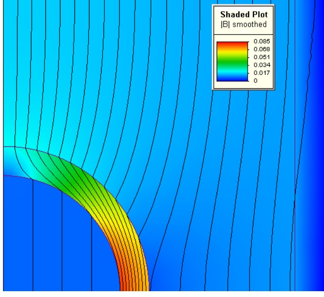
This process is mainly associated with plotting the results of the solutions on a graph and representing the area of the domain that has higher or lower concentrations of the deformations. It gives a clear visual of the critical areas.
Finite element formulation from a differential equation
Every physical system's behavior can be represented in the form of partial differential equations (PDEs). These PDEs may be first-order, second-order, third-order, and so on. These PDEs can be solved to determine the unknowns. There are a few steps involved in the FEA method to determine the solutions of these PDEs.
- Guessing the trial solution of the problem: The exact behavior of the system is known, hence a rough solution is assumed. Generally, a polynomial function is considered. The function is given as,
- As the selected function is a guess, it will cause an error (residue) in the solution which needs to be considered. This selected trial solution will not satisfy the differential equation and the boundary conditions. A popular technique of minimizing the residual is to use the Galerkin technique. It is given by where is the weights and is the domain residual.
- Determining the unknown parameters such as by applying the boundary conditions.
Application of FEA
With the increasing complexity of structural problems, FEA has gained a reputation in analysis and simulations. Many of the analysis software integrates the FEA for ease of solutions for such problems that have a very discontinued and complex domain. These domains are discretized by millions of finite elements that require a computer for solving the equations. Some of the applications of FEA are outlined below.
- Computational fluid dynamics (CFD): The structures in civil engineering applications need to withstand external aerodynamic effects of forces due to wind and hydrostatic effects due to water. These effects must be analyzed for the same design of the structures. The CFD analysis provided by software predicts accurately the behavior of such a system under such conditions.
- Modal analysis: Due to the flow of wind past the structural members, and depending upon Reynold's number of the flow, vibrations in the structures are induced, these vibrations are also known as vortex-induced vibrations. A thorough modal analysis will help in determining the natural frequencies of the component system at which the system may fail due to resonance.
- Static structural analysis: This is intended to determine the stresses and deformations in the structure due to external loading conditions. This analysis can also be used for the analysis of a prototype. The prototype is a dummy model of the structure on a smaller scale.
Context and Applications
- Bachelor in Science in Physics
- Master in Science in Physics
- Bachelors in Technology (Civil Engineering)
- Masters in Technology (Civil Engineering)
Practice Problems
1. Which of the following is the final step in the FEA?
a) Discretization
b) Assembling
c) Solution
d) Post-processing
Correct option: d
Explanation: The final step in the FEA is post-processing, where the results of the solution are viewed in the form of graphical representations.
2. Which of the following FEA specially deals with fluid flow applications?
a) Modal analysis
b) Static harmonic analysis
c) Transient harmonic analysis
d) CFD
Correct option: d
Explanation: CFD is known as computational fluid dynamics, a finite element method of analyzing fluid flow behavior.
3. Which of the following is a model of the structure on a smaller scale?
a) Prototype
b) Structural modal
c) Dummy structure
d) None of these
Correct option: a
Explanation: The effect of forces on the structure can be modeled and simulated in a prototype, which is a small-scaled model of a structure.
4. The behavior of any physical system can be represented by PDEs. Is the statement true or false?
Correct answer: True
Explanation: PDEs are used to represent the behavior of the physical system.
5. Which of the following problem is solved by modal analysis?
a) Fluid flow problem
b) Structural analysis problem
c) Vibration problem
d) None of these
Correct option: c
Explanation: The vibration analysis of a structure is termed modal analysis.
Related concepts
- Eurocodes in structural design and number of Eurocodes
- International journal of Civil Engineering and Technology
- International Journal of vibration and control
Want more help with your civil engineering homework?
*Response times may vary by subject and question complexity. Median response time is 34 minutes for paid subscribers and may be longer for promotional offers.
Search. Solve. Succeed!
Study smarter access to millions of step-by step textbook solutions, our Q&A library, and AI powered Math Solver. Plus, you get 30 questions to ask an expert each month.
Finite element analysis and design
Finite Element Formulation for Structural Members
Design of Structures using FEA
Design of structures using FEA Homework Questions from Fellow Students
Browse our recently answered Design of structures using FEA homework questions.
Search. Solve. Succeed!
Study smarter access to millions of step-by step textbook solutions, our Q&A library, and AI powered Math Solver. Plus, you get 30 questions to ask an expert each month.