
Videos
In each case, identify any two-force members, and then draw the free body diagrams of each member of the frame.
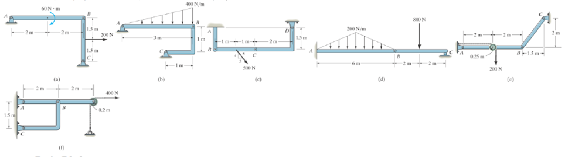
Prob. P6-3
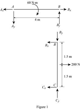
(a)
To identify and draw: The two force members and the free body diagrams of each member of the frame.
Explanation of Solution
Assumptions:
- Consider the state of member as tension where the force is pulling the member and as compression where the force is pushing the member.
- Consider the force indicating right side as positive and left side as negative in horizontal components of forces.
- Consider the force indicating upside is taken as positive and downside as negative in vertical components of forces.
Show the free body diagram of the member of the frame as in Figure (1).
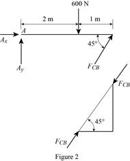
(b)
To identify and draw: The two force members and the free body diagrams of each member of the frame.
Explanation of Solution
Assumptions:
- Consider the state of member as tension where the force is pulling the member and as compression where the force is pushing the member.
- Consider the force indicating right side as positive and left side as negative in horizontal components of forces.
- Consider the force indicating upside is taken as positive and downside as negative in vertical components of forces.
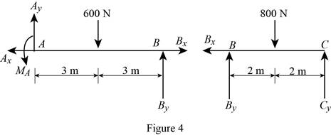
The member CB is a two force member.
Show the free body diagram of the members of the frame as in Figure (2).
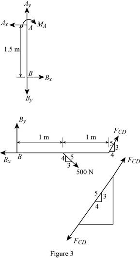
(c)
To identify and draw: The two force members and the free body diagrams of each member of the frame.
Explanation of Solution
Assumptions:
- Consider the state of member as tension where the force is pulling the member and as compression where the force is pushing the member.
- Consider the force indicating right side as positive and left side as negative in horizontal components of forces.
- Consider the force indicating upside is taken as positive and downside as negative in vertical components of forces.
The member CD is a two force member.
Show the free body diagram of the members of the frame as in Figure (3).
(d)
To identify and draw: The two force members and the free body diagrams of each member of the frame.
Explanation of Solution
Assumptions:
- Consider the state of member as tension where the force is pulling the member and as compression where the force is pushing the member.
- Consider the force indicating right side as positive and left side as negative in horizontal components of forces.
- Consider the force indicating upside is taken as positive and downside as negative in vertical components of forces.
Show the free body diagram of the members of the frame as in Figure (4).
(e)
To identify and draw: The two force members and the free body diagrams of each member of the frame.
Explanation of Solution
Assumptions:
- Consider the state of member as tension where the force is pulling the member and as compression where the force is pushing the member.
- Consider the force indicating right side as positive and left side as negative in horizontal components of forces.
- Consider the force indicating upside is taken as positive and downside as negative in vertical components of forces.
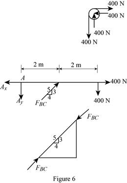
The member BC is a two force member.
Show the free body diagram of the members of the frame as in Figure (5).

(f)
To identify and draw: The two force members and the free body diagrams of each member of the frame.
Explanation of Solution
Assumptions:
- Consider the state of member as tension where the force is pulling the member and as compression where the force is pushing the member.
- Consider the force indicating right side as positive and left side as negative in horizontal components of forces.
- Consider the force indicating upside is taken as positive and downside as negative in vertical components of forces.
The member BC is a two force member.
Show the free body diagram of the members of the frame as in Figure (5).
Want to see more full solutions like this?
Chapter 6 Solutions
INTERNATIONAL EDITION---Engineering Mechanics: Statics, 14th edition (SI unit)
Additional Engineering Textbook Solutions
Mechanics of Materials (10th Edition)
Statics and Mechanics of Materials (5th Edition)
Engineering Mechanics: Dynamics (14th Edition)
Mechanics of Materials
Automotive Technology: Principles, Diagnosis, and Service (5th Edition)
Automotive Technology: Principles, Diagnosis, And Service (6th Edition) (halderman Automotive Series)


- Find the minimum force P required for impending motion of the block up the inclined surface, given: Mblock = 65 kg, θ = 52 °, μ = 0.4arrow_forwardThe disk B has a mass of 20 kg and is supported on the smooth cylindrical surface by a spring with stiffness k= 400 N/m and unstretched length l0= 1 m. The spring remains in the horizontal position since its end A is attached to the small roller guide which has negligible weight. Determine the equilibrium angle of the roller.arrow_forwardDraw the Free Body Diagramarrow_forward
- If the gap between C and the rigid wall at D is initially 0.15 mm, determine the support reactions at A and D when the force P = 200 kN is applied. The assembly is made of solid A-36 steel cylinders.arrow_forwardThe smooth uniform rod AB is supported by a ball-and-socket joint at A, the wall at B, and the cableBC. Determine the components of reactions at A, the tension in the cable, and the normal reaction at Bif the rod has a mass of 20 kg. Provide a free-body-diagramarrow_forwardSHOW THE FREE BODY DIAGRAMarrow_forward
- Draw the free-body diagram of each object and determine the components of the support reactions.arrow_forwardThe two A-36 steel bars have a thickness of 1 in. and a width of 4 in. They are designed to act as a spring for the machine which exerts a force of 4 kip on them at A and B. If the supports exert only vertical forces on the bars, determine the maximum deflection of the bottom bar.arrow_forwardThe A-36 steel pipe has an outer radius of 20 mm and an inner radius of 15 mm. If it fits snugly between the fixed walls before it is loaded, determine the reaction at the walls when it is subjected to the load shown.arrow_forward
- Draw the Free-Body Diagram if the weight acts on point Garrow_forwardThe jib crane is supported by a pin at C and rod AB. If the load has a mass of 1.89 Mg with its center of mass located at G. If x = 5 m, determine the following: 9.1 The force developed in rod AB on the crane is Blank 1 kN. 9.2 The support reaction at pin C is Blank 2 kN. 9.3 The jib crane is supported by a pin at C and rod AB. The rod can withstand a maximum tension of 38 kN. If the load has a mass of 2 Mg, with its center of mass located at G, determine the maximum allowable distance x in meters.arrow_forwardThe sign has a mass of 150kg with center of mass in G. Draw the free body diagram and determine the components along x,y,z of the reaction in ball joint A as well as the tensile strength in wires BC and BD(Caution : they are two different wires). g=9.81m/s²arrow_forward
 International Edition---engineering Mechanics: St...Mechanical EngineeringISBN:9781305501607Author:Andrew Pytel And Jaan KiusalaasPublisher:CENGAGE L