
(a)
Mention the resistors connected in series for the given circuits in Figure P3.1.
(a)
Explanation of Solution
Given data:
Refer to the given circuit shown in Figure P3.1.
Calculation:
Figure P3.1(a):
Refer to Figure P3.1(a) in the textbook, the resistors connected in series are
Figure P3.1(b):
Refer to Figure P3.1(b) in the textbook, the resistors connected in series are
Figure P3.1(c):
The Figure P3.1(c) in the textbook is shown in Figure 1.
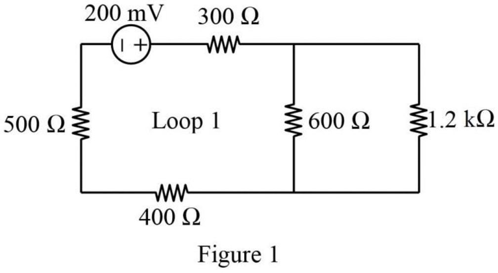
In Figure 1, the resistors connected in series (Loop 1) are the
Figure P3.1(d):
Refer to Figure P3.1(d) in the textbook, the resistors connected in series are
Conclusion:
Thus, the resistors connected in series for the given circuits are mentioned.
(b)
Find the equivalent resistors by simplifying the circuits of the series-connected resistors in Figure P3.1.
(b)
Explanation of Solution
Given data:
Refer to the given circuit shown in Figure P3.1.
Calculation:
Figure P3.1(a):
Refer to Figure P3.1(a) in the textbook,
Similarly,
The modified circuit is shown in Figure 2.
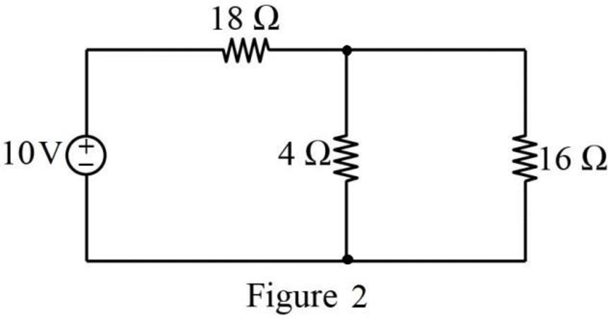
Figure P3.1(b):
Refer to Figure P3.1(b) in the textbook, the resistors
The modified circuit is shown in Figure 3.
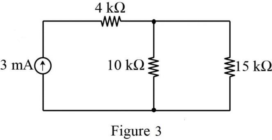
Figure P3.1(c):
Refer to Figure P3.1(c) in the textbook, the resistors
The modified circuit is shown in Figure 4.
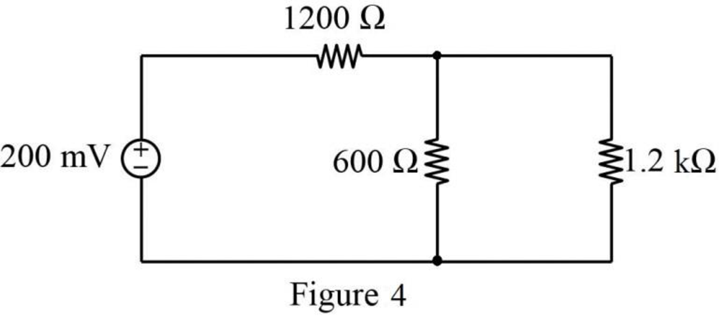
Figure P3.1(d):
Refer to Figure P3.1(d) in the textbook, the resistors
Similarly, the resistors
The modified circuit is shown in Figure 5.
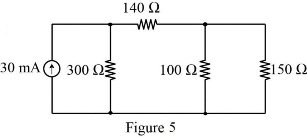
Conclusion:
Thus, the simplified circuit is drawn for the series-connected resistors with equivalent resistors.
Want to see more full solutions like this?
Chapter 3 Solutions
Electric Circuits. (11th Edition)
Additional Engineering Textbook Solutions
Electric Circuits. (11th Edition)
Degarmo's Materials And Processes In Manufacturing
Starting Out with C++ from Control Structures to Objects (9th Edition)
Modern Database Management
Starting Out with Java: From Control Structures through Data Structures (4th Edition) (What's New in Computer Science)
INTERNATIONAL EDITION---Engineering Mechanics: Statics, 14th edition (SI unit)
- For the circuit shown in figure below: C R + 1. Apply Kirchhoff's voltage low (KVL) if R 10, L = 0.1 H, C= 0.01 F and V=10. 2. Write the 2nd order differential equation (DE) that describe the current of the circuit (i). 3. Solve the DE to find the current (i) assume i(0) = i'(0) = 0. 4. Replace the DC source with AC source V = 10sin40t then solve the DE.arrow_forwardQ1. In the Pi model of the Medium-Length Line the radius of the conductors of the lines are approximately r=r' and f = 50Hz, calculate the value of BC in the transmission matrix T = [B](NOTE: Line is without loss and length of it is 100km and π = 3).arrow_forwardDon't use ai to answer I will report you answerarrow_forward
- Need a soluarrow_forwardThe frequency of rotor current in an induction motor is: a; slip times the frequency of stator current b: slip times the frequency of supply c; One by slip times the frequency of stator current d; One by slip times the frequency of supplyarrow_forwardFor induction motors, the following is true: a: Should be essentially a constant speed motor b; Its speed reduces to some extent with increase in load c; Does not need to be synchronized d; All of thesearrow_forward
 Introductory Circuit Analysis (13th Edition)Electrical EngineeringISBN:9780133923605Author:Robert L. BoylestadPublisher:PEARSON
 Delmar's Standard Textbook Of ElectricityElectrical EngineeringISBN:9781337900348Author:Stephen L. HermanPublisher:Cengage Learning
 Programmable Logic ControllersElectrical EngineeringISBN:9780073373843Author:Frank D. PetruzellaPublisher:McGraw-Hill Education
 Fundamentals of Electric CircuitsElectrical EngineeringISBN:9780078028229Author:Charles K Alexander, Matthew SadikuPublisher:McGraw-Hill Education
 Electric Circuits. (11th Edition)Electrical EngineeringISBN:9780134746968Author:James W. Nilsson, Susan RiedelPublisher:PEARSON
 Engineering ElectromagneticsElectrical EngineeringISBN:9780078028151Author:Hayt, William H. (william Hart), Jr, BUCK, John A.Publisher:Mcgraw-hill Education,


