
Physics for Scientists and Engineers with Modern Physics
4th Edition
ISBN: 9780131495081
Author: Douglas C. Giancoli
Publisher: Addison-Wesley
expand_more
expand_more
format_list_bulleted
Videos
Textbook Question
Chapter 26, Problem 36P
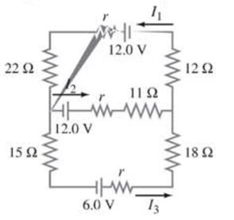
(III) (a) Determine the currents I1, I2, and I3 in Fig. 26–53. Assume the internal resistance of each battery is r = 1.0 Ω. (b) What is the terminal voltage of the 6.0-V battery?
Expert Solution & Answer
Want to see the full answer?
Check out a sample textbook solution
Students have asked these similar questions
What is the potential difference between points a and d in Fig. 19-57 and (b) what is the terminal voltage of each battery?
(II) Determine the terminal voltage of each battery in
Fig. 19–54.
r= 2.0 2
E = 18 V
R=4.8 2
r= 1.0 2
FIGURE 19-54
E = 12 V
Problem 26.
(II) If 21.0 V is applied across
the whole network of Fig. 19–63,
calculate (a) the voltage across
each capacitor and (b) the charge
on each capacitor.
C =
3.00 μF
C2 =
4.00 μF
C3 =
2.00 μF
FIGURE 19-63
V=
Problems 39 and 40.
-21.0 V-
Chapter 26 Solutions
Physics for Scientists and Engineers with Modern Physics
Ch. 26.1 - Repeat Example 261 assuming now that the...Ch. 26.2 - You have a 10- and a 15- resistor. What is the...Ch. 26.3 - Write the equation for the lower loop abcdefga of...Ch. 26.4 - If the jumper cables of Example 2610 were...Ch. 26.5 - In 10 times constants, the charge on the capacitor...Ch. 26 - Explain why birds can sit on power lines safely,...Ch. 26 - Discuss the advantages and disadvantages of...Ch. 26 - If all you have is a 120-V line, would it be...Ch. 26 - Two lightbulbs of resistance R1 and R2 (R2 R1)...Ch. 26 - Household outlets are often double outlets. Are...
Ch. 26 - With two identical lightbulbs and two identical...Ch. 26 - If two identical resistors are connected in series...Ch. 26 - You have a single 60-W bulb on in your room. How...Ch. 26 - When applying Kirchhoffs loop rule (such as in...Ch. 26 - Compare and discuss the formulas for resistors and...Ch. 26 - For what use are batteries connected in series?...Ch. 26 - Can the terminal voltage of a battery ever exceed...Ch. 26 - Explain in detail how you could measure the...Ch. 26 - In an RC circuit, current flows from the battery...Ch. 26 - Given the circuit shown in Fig. 2634, use the...Ch. 26 - Figure 2635 is a diagram of a capacitor (or...Ch. 26 - Design a circuit in which two different switches...Ch. 26 - What is the main difference between an analog...Ch. 26 - What would happen if you mistakenly used an...Ch. 26 - Explain why an ideal ammeter would have zero...Ch. 26 - A voltmeter connected across a resistor always...Ch. 26 - A small battery-operated flashlight requires a...Ch. 26 - Different lamps might have batteries connected in...Ch. 26 - Prob. 1PCh. 26 - (I) Four 1.50-V cells are connected in series to a...Ch. 26 - (II) A 1.5-V dry cell can be tested by connecting...Ch. 26 - (II) What is the internal resistance of a 12.0-V...Ch. 26 - (I) A 650- and a 2200- resistor are connected in...Ch. 26 - (I) Three 45- lightbulbs and three 65- lightbulbs...Ch. 26 - (I) Suppose that you have a 680-, a 720-, and a...Ch. 26 - (I) How many 10- resistors must be connected in...Ch. 26 - (II) Suppose that you have a 9.0-V battery and you...Ch. 26 - Three 1.70-k resistors can be connected together...Ch. 26 - (II) A battery with an emf of 12.0 V shows a...Ch. 26 - (II) Eight identical bulbs are connected in series...Ch. 26 - (II) Eight bulbs are connected in parallel to a...Ch. 26 - (II) The performance of the starter circuit in an...Ch. 26 - (II) A close inspection of an electric circuit...Ch. 26 - (II) Determine (a) the equivalent resistance of...Ch. 26 - (II) A 75-W, 110-V bulb is connected in parallel...Ch. 26 - (II) (a) Determine the equivalent resistance of...Ch. 26 - (II) Whal is the net resistance of the circuit...Ch. 26 - (II) Calculate the current through each resistor...Ch. 26 - (II) The two terminals of a voltage source with...Ch. 26 - (II) Two resistors when connected in series to a...Ch. 26 - (III) Three equal resistors (R) are connected to a...Ch. 26 - (III) A 2.8-k and a 3.7-k resistor are connected...Ch. 26 - (III) Consider the network of resistors shown in...Ch. 26 - (III) You are designing a wire resistance heater...Ch. 26 - (I) Calculate the current in the circuit of Fig....Ch. 26 - (II) Determine the terminal voltage of each...Ch. 26 - (II) For the circuit shown in Fig. 2647, find the...Ch. 26 - (II) (a) A network of five equal resistors R is...Ch. 26 - (II) (a) What is the potential difference between...Ch. 26 - (II) Calculate the currents in each resistor of...Ch. 26 - (II) Determine the magnitudes and directions of...Ch. 26 - (II) Determine the magnitudes and directions of...Ch. 26 - (II) A voltage V is applied to n identical...Ch. 26 - (III) (a) Determine the currents I1, I2, and I3 in...Ch. 26 - (III) What would the current I1 be in Fig. 2653 if...Ch. 26 - (III) Determine the current through each of the...Ch. 26 - (III) If the 25- resistor in Fig. 2654 is shorted...Ch. 26 - (III) Twelve resistors, each of resistance R, are...Ch. 26 - (III) Determine the net resistance in Fig. 2656...Ch. 26 - (II) Suppose two batteries, with unequal emfs of...Ch. 26 - (I) Estimate the range of resistance needed to...Ch. 26 - (II) In Fig. 2658 (same as Fig. 2617a), the total...Ch. 26 - (II) Two 3.8-F capacitors, two 2.2-k resistors,...Ch. 26 - (II) How long does it take for the energy stored...Ch. 26 - (II) A parallel-plate capacitor is filled with a...Ch. 26 - (II) The RC circuit of Fig. 2659 (same as Fig....Ch. 26 - (II) Consider the circuit shown in Fig. 2660,...Ch. 26 - (III) Determine the time constant for charging the...Ch. 26 - (III) Two resistors and two uncharged capacitors...Ch. 26 - (III) Suppose the switch S in Fig. 2662 is closed....Ch. 26 - (I) An ammeter has a sensitivity of 35,00 /V. What...Ch. 26 - (I) What is the resistance of a voltmeter on the...Ch. 26 - (II) A galvanometer has a sensitivity of 45 k/V...Ch. 26 - (II) A galvanometer has an internal resistance of...Ch. 26 - (II) A particular digital meter is based on an...Ch. 26 - (II) A milliammeter reads 25 mA full scale. It...Ch. 26 - (II) A 45-V battery of negligible internal...Ch. 26 - (II) An ammeter whose internal resistance is 53 ...Ch. 26 - (II) A battery with E=12.0V and internal...Ch. 26 - (II) A 12.0-V battery (assume the internal...Ch. 26 - (III) Two 9.4-k resistors are placed in series and...Ch. 26 - (III) When the resistor R in Fig. 2664 is 35 , the...Ch. 26 - Suppose that you wish to apply a 0.25-V potential...Ch. 26 - A three-way lightbulb can produce 50 W, 100 W, or...Ch. 26 - Suppose you want to run some apparatus that is 65...Ch. 26 - For the circuit shown in Fig. 2618a, show that the...Ch. 26 - A heart pacemaker is designed to operate at 72...Ch. 26 - Prob. 70GPCh. 26 - A Wheatstone bridge is a type of bridge circuit...Ch. 26 - An unknown length of platinum wire 1.22 mm in...Ch. 26 - The internal resistance of a 1.35-V mercury cell...Ch. 26 - How many 12-W resistors, each of the same...Ch. 26 - A solar cell, 3.0 cm square, has an output of 350...Ch. 26 - A power supply has a fixed output voltage of 12.0...Ch. 26 - The current through the 4.0-k resistor in Fig....Ch. 26 - A battery produces 40.8 V when 7.40 A is drawn...Ch. 26 - In the circuit shown in Fig. 2668, the 33-...Ch. 26 - The current through the 20- resistor in Fig. 2669...Ch. 26 - (a) A voltmeter and an ammeter can be connected as...Ch. 26 - (a) What is the equivalent resistance of the...Ch. 26 - A flashlight bulb rated at 2.0 W and 3.0 V is...Ch. 26 - Some light-dimmer switches use a variable resistor...Ch. 26 - A potentiometer is a device to precisely measure...Ch. 26 - Electronic devices often use an RC circuit to...Ch. 26 - The circuit shown in Fig. 2676 is a primitive...Ch. 26 - Determine the current in each resistor of the...Ch. 26 - In the circuit shown in Fig. 2678, switch S is...Ch. 26 - Figure 2679 shows the circuit for a simple...Ch. 26 - Measurements made on circuits that contain large...Ch. 26 - A typical voltmeter has an internal resistance of...Ch. 26 - (II) An RC series circuit contains a resistor R =...
Additional Science Textbook Solutions
Find more solutions based on key concepts
How much heat did the body supply to warm air.
College Physics: A Strategic Approach (3rd Edition)
The longest focal length lens that will work.
Physics (5th Edition)
If acceleration is proportional to the net force or is equal to net force.
Conceptual Physics (12th Edition)
An ideal gas is made to undergo the cyclic process shown in Figure 1.10 (a). For each of the steps A, B, and C,...
An Introduction to Thermal Physics
A 40-W fluorescent lamp has power factor 0.85 and operates from the 120-V rms AC power line. How much current d...
Essential University Physics: Volume 2 (3rd Edition)
3. What is free-fall, and why does it make you weightless? Briefly describe why astronauts are weightless in th...
The Cosmic Perspective (8th Edition)
Knowledge Booster


Learn more about
Need a deep-dive on the concept behind this application? Look no further. Learn more about this topic, physics and related others by exploring similar questions and additional content below.Similar questions
- (a) In Fig. 25-19a, are capacitors 1 and 3 in series? (b) In the same (a) (b) (c) (d) HHarrow_forwardFor the circuit shown in Fig. 19–80, determine (a) the current through the 16-V battery and (b) the potential difference between 13 k2 b 10 k2 a points a and b, Va - Vp. 16 V= - 21 V FIGURE 19-80 Problem 82. 12 V ww 18 k2 12 k2arrow_forward5. (II) What is the ratio of the voltage V, across capacitor C, in Fig. 19–65 to the voltage V2 across capacitor C,? C2 = 1.0 µF C1 = 1.0 μF 10 V . +C3 = 1.0 µF FIGURE 19-65 Problem 45.arrow_forward
- A flashlight bulb rated at 2.0 W and 3.0 V is operated by a 9.0-V battery. To light the bulb at its rated voltage and power, a resistor R is connected in series as shown in Fig. 19–85. What value should the resistor have? R FIGURE 19-85 Problem 87. 9.0 Varrow_forward(III) Two resistors and two uncharged capacitors are arranged as shown in Fig. 19–72. Then a potential difference of 24 V is applied across the combination as shown. (a) What is the potential at point a with switch S open? (Let V = 0 at the negative terminal of the source.) (b) What is the potential at point b with the switch open? (c) When the switch is closed, what is the final potential of point b? (d) How much + charge flows through 24 V 8.8 N 0.48 μF a S the switch S after it is closed? 4.4 2 0.36 μF FIGURE 19–72 Problem 58.arrow_forwardIn the circuit shown (a) find the charge on each capacitor; (b) voltage across each capacitor and (c) voltage of the battery. Voltage acioss suF= 6V. 4uF A 3MF tcarrow_forward
- Te-Learning Portal Courses - Reports e-Services ▼ Academic Departments - ETC - CIMS Salim During an experiment to verify Ohm's law, the voltage supplied and the current through a circuit are measured. [Voltage is measured in Volt (V) and current in Ampere (A)]. ww R on Battery The measured value of the current is I = 3.1 ± 0.2 A and that of the voltage is V = 14 0.5 V. The resistance of the circuit (in N) can be calculated using the formula, R = V/I, Calculate the, a) Resistance (in 2) = b) Fractional uncertainty in the resistance = c) Absolute uncertainty (in 2) in the resistance=arrow_forwardIn the circuit shown in Fig. 19–93, C¡ = 1.0 µF, C2 = 2.0 µF, C3 = 2.4 µF, and a voltage_ Vab = 24 V is applied across points a and b. After C, is fully charged, the switch is thrown to the right. What is the final charge and potential differ- ence on each capacitor? ao C2 FIGURE 19-93 C3 Problem 97. boarrow_forward(b) A student has three capacitors. Two of the capacitors have a capacitance of 4.0 µF and one has a capacitance of 8.0 µF. Draw labelled circuit diagrams, one in each case, to show how the three capacitors may be connected to give a total capacitance of: (i) 1.6uF (ii) 10µF.arrow_forward
- If Vab=10 Volts according to the circuit in the figure, find the charge accumulated on the 6 uF capacitor? a 3µF 28µF 14µF lµF 6µF 3 - 3µF, 7µF 3µF 18µF O a) 5 ОВ) 10 O NS) 160/21 OD) 4.84.10^(-6) O TO) 4arrow_forward7 For each circuit in Fig. 25-21, are the capacitors connected in series, in parallel, or in neither mode? (c) (b) Figure 25-21 Question 7. (a)arrow_forward(b) 50 2 shown in the Figure Q11(b). Find the equivalent resistance across AB. (i) (ii) Find the voltage VAB across AB. 15v Vs Rs R2 A B R1 R3 R1 = 20 92, R2 = 30 2 and R3 = + VABarrow_forward
arrow_back_ios
SEE MORE QUESTIONS
arrow_forward_ios
Recommended textbooks for you
 College PhysicsPhysicsISBN:9781305952300Author:Raymond A. Serway, Chris VuillePublisher:Cengage Learning
 University Physics (14th Edition)PhysicsISBN:9780133969290Author:Hugh D. Young, Roger A. FreedmanPublisher:PEARSON
 Introduction To Quantum MechanicsPhysicsISBN:9781107189638Author:Griffiths, David J., Schroeter, Darrell F.Publisher:Cambridge University Press
 Physics for Scientists and EngineersPhysicsISBN:9781337553278Author:Raymond A. Serway, John W. JewettPublisher:Cengage Learning
 Lecture- Tutorials for Introductory AstronomyPhysicsISBN:9780321820464Author:Edward E. Prather, Tim P. Slater, Jeff P. Adams, Gina BrissendenPublisher:Addison-Wesley
 College Physics: A Strategic Approach (4th Editio...PhysicsISBN:9780134609034Author:Randall D. Knight (Professor Emeritus), Brian Jones, Stuart FieldPublisher:PEARSON
College Physics
Physics
ISBN:9781305952300
Author:Raymond A. Serway, Chris Vuille
Publisher:Cengage Learning
University Physics (14th Edition)
Physics
ISBN:9780133969290
Author:Hugh D. Young, Roger A. Freedman
Publisher:PEARSON
Introduction To Quantum Mechanics
Physics
ISBN:9781107189638
Author:Griffiths, David J., Schroeter, Darrell F.
Publisher:Cambridge University Press
Physics for Scientists and Engineers
Physics
ISBN:9781337553278
Author:Raymond A. Serway, John W. Jewett
Publisher:Cengage Learning
Lecture- Tutorials for Introductory Astronomy
Physics
ISBN:9780321820464
Author:Edward E. Prather, Tim P. Slater, Jeff P. Adams, Gina Brissenden
Publisher:Addison-Wesley
College Physics: A Strategic Approach (4th Editio...
Physics
ISBN:9780134609034
Author:Randall D. Knight (Professor Emeritus), Brian Jones, Stuart Field
Publisher:PEARSON
How To Solve Any Resistors In Series and Parallel Combination Circuit Problems in Physics; Author: The Organic Chemistry Tutor;https://www.youtube.com/watch?v=eFlJy0cPbsY;License: Standard YouTube License, CC-BY