
Fundamentals of Physics, Volume 1, Chapter 1-20
10th Edition
ISBN: 9781118233764
Author: David Halliday
Publisher: WILEY
expand_more
expand_more
format_list_bulleted
Concept explainers
Videos
Textbook Question
Chapter 25, Problem 22P
In Fig. 25-37, V = 10 V, C1 = 10 μF, and C2 = C3 = 20 μF. Switch S is first thrown to the left side until capacitor 1 reaches equilibrium. Then the switch is thrown to the right. When equilibrium is again reached, how much charge is on capacitor 1?
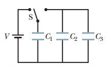
Figure 25-37 Problem 22.
Expert Solution & Answer
Want to see the full answer?
Check out a sample textbook solution
Students have asked these similar questions
*22 In Fig. 25-37, V = 10 V, C = 10
uF, and C = C, = 20 µF. Switch S is
first thrown to the left side until capac-
itor 1 reaches equilibrium. Then the
switch is thrown to the right. When
equilibrium is again reached, how
much charge is on capacitor 1?
Figure 25-37 Problem 22.
15. In Fig. 25-51, V =9.0 V, C1=C2 =30 µF, and C3=C4 =15 µF. What is the (i) charge on capacitor 4? (ii) charge on
capacitor 2? (ii) voltage drop across C3, and (iv) voltage drop across C1 ?
EE
C4
V
Figure 25-51 Problem 57.
14. In Fig. 25-30, the battery has a potential difference of V = 10.0 V and the five capacitors each have a
capacitance of 10.0 µF. What is the charge on (a) capacitor 1 and (b) capacitor 2?
Figure 25-30 Problem 14.
Chapter 25 Solutions
Fundamentals of Physics, Volume 1, Chapter 1-20
Ch. 25 - Figure 25-18 shows plots of charge versus...Ch. 25 - What is Ceq of three capacitors, each of...Ch. 25 - a In Fig. 25-19a are capacitors 1 and 3 in series?...Ch. 25 - Figure 25-20 shows three circuits, each consisting...Ch. 25 - Initially, a single capacitance C1 is wired to a...Ch. 25 - Repeat Question 5 for C2 added in series rather...Ch. 25 - For each circuit in Fig. 25-21, are the capacitors...Ch. 25 - Figure 25-22 shows an open switch, a battery of...Ch. 25 - A parallel-plate capacitor is connected to a...Ch. 25 - When a dielectric slab is inserted between the...
Ch. 25 - You are to connect capacitances C1 and C2, with...Ch. 25 - The two metal objects in Fig. 25-24 have net...Ch. 25 - The capacitor in Fig. 25-25 has a capacitance of...Ch. 25 - SSM A parallel-plate capacitor has circular plates...Ch. 25 - The plates of spherical capacitor have radii 38.0...Ch. 25 - What is the capacitance of a drop that results...Ch. 25 - You have two flat metal plates, each of area...Ch. 25 - If an uncharged parallel-plate capacitor...Ch. 25 - How many 1.00 F capacitors must be connected in...Ch. 25 - Each of the uncharged capacitors in Fig. 25-27 has...Ch. 25 - In Fig. 25-28, find the equivalent capacitance of...Ch. 25 - In Fig. 25-29, find the equivalent capacitance of...Ch. 25 - Two parallel-plate capacitors, 6.0 F each, are...Ch. 25 - SSM ILW A 100 pF capacitor is charged to a...Ch. 25 - GO In Fig. 25-30, the battery has a potential...Ch. 25 - GO In Fig. 25-31, a 20.0 V battery is connected...Ch. 25 - Plot in Fig. 25-32a gives the charge q that can be...Ch. 25 - GO In Fig. 25-29, a potential difference of V =...Ch. 25 - Figure 25-33 shows a circuit section of four...Ch. 25 - GO In Fig. 25-34, the battery has potential...Ch. 25 - Figure 25-35 shows a variable "airgap capacitor...Ch. 25 - SSM WWWIn Fig. 25-36, capacitances are charged C1...Ch. 25 - In Fig. 25-37, V = 10 V, C1 = 10 F, and C2 = C3 =...Ch. 25 - The capacitors in Fig. 25-38 are initially...Ch. 25 - GO Figure 25-39 represents two air-filled...Ch. 25 - GO In Fig. 25-40, two parallel-plate capacitors...Ch. 25 - GO Capacitor 3 in Fig. 25-41a is a variable...Ch. 25 - GO Figure 25-42 shows a 12.0 V battery and four...Ch. 25 - GO Figure 25-43 displays a 12.0 V battery and 3...Ch. 25 - What capacitance is required to store an energy of...Ch. 25 - How much energy is stored in 1.00 m3of air due to...Ch. 25 - SSMA 2.0 F capacitor and a 4.0 F capacitor are...Ch. 25 - A parallel-plate air-filled capacitor having area...Ch. 25 - A charged isolated metal sphere of diameter 10 cm...Ch. 25 - In Fig. 25-28, a potential difference V = 100 V is...Ch. 25 - Assume that a stationary electron is a point of...Ch. 25 - As a safety engineer, you must evaluate the...Ch. 25 - SSM ILW WWW The parallel plates in a capacitor,...Ch. 25 - In Fig. 25-29, a potential difference V = 100 V is...Ch. 25 - Go In Fig. 25-45, C1 = 10.0 F, C2= 20.0 F, and C3...Ch. 25 - An air-filled parallel-plate capacitor has a...Ch. 25 - SSMA coaxial cable used in a transmission line has...Ch. 25 - A parallel-plate air-filled capacitor has a...Ch. 25 - Given a 7.4 pF air-filled capacitor, you are asked...Ch. 25 - You are asked to construct a capacitor having a...Ch. 25 - A certain parallel-plate capacitor is filled with...Ch. 25 - In Fig. 25-46, how much charge is stored on the...Ch. 25 - SSM ILWA certain substance has a dielectric...Ch. 25 - Figure 25-47 shows a parallel-plate capacitor with...Ch. 25 - Figure 25-48 shows a parallel-plate capacitor with...Ch. 25 - Go Figure 25-49 shows a parallel-plate capacitor...Ch. 25 - SSM WWWA parallel-plate capacitor has a...Ch. 25 - For the arrangement of Fig. 25-17, suppose that...Ch. 25 - A parallel-plate capacitor has plates of area 0.12...Ch. 25 - Two parallel plates of area 100 cm2 are given...Ch. 25 - The space between two concentric conducting...Ch. 25 - In Fig. 25-50, the battery potential difference V...Ch. 25 - SSMIn Fig. 25-51, V = 9.0 V, C1 = C2= 30 F, and C3...Ch. 25 - a If C = 50 F in Fig. 25-52, what is the...Ch. 25 - In Fig.25-53, V = 12 V, C1 = C4 = 2.0 F, C2 = 4.0...Ch. 25 - The chocolate crumb mystery. This troy begins with...Ch. 25 - Figure 25-54 shows capacitor 1 C1 = 8.00 F,...Ch. 25 - Two air-filled, parallel-plate capacitors are to...Ch. 25 - Two parallel-plate capacitors, 6.0 F each, are...Ch. 25 - GO In Fig. 25-55, V = 12 V, C1 = C5 = C6 = 6.0 F,...Ch. 25 - SSM In Fig.25-56, the parallel-plate capacitor of...Ch. 25 - A cylindrical capacitor has radii a and b as in...Ch. 25 - A capacitor of capacitance C1 = 6.00 F is...Ch. 25 - Repeat Problem 67 for the same two capacitors but...Ch. 25 - A certain capacitor is charged to a potential...Ch. 25 - Aslab of copper of thickness b = 2.00 mm is thrust...Ch. 25 - Repeat Problem 70, assuming that a potential...Ch. 25 - A potential difference of 300 V is applied to a...Ch. 25 - Figure 25-58 shows a four capacitor arrangement...Ch. 25 - You have two plates of copper, a sheet of mica...Ch. 25 - A capacitor of unknown capacitance Cis charged to...Ch. 25 - A 10 V battery is connected to a series of n...Ch. 25 - SSM In Fig. 25-59, two parallel-plate capacitors A...Ch. 25 - You have many 2.0F capacitors, each capable of...Ch. 25 - A parallel-plate capacitor has charge q and plate...Ch. 25 - A capacitor is charged until its stored energy is...
Additional Science Textbook Solutions
Find more solutions based on key concepts
Assuming a constant temperature coefficient of resistivity, what is the maximum percent decrease in the resista...
College Physics
Predict what will happen if the net charge on ball 2 isreduced to zero. Make asketch to illustrate youranswer.
Tutorials in Introductory Physics
Figure 9.32 shows the energy minimum of molecular NaCl, through which a parabola has been drawn. Following the ...
MODERN PHYSICS (LOOSELEAF)
The value of the charge q3 for the net force on it to be 4.00 μΝ .
Sears And Zemansky's University Physics With Modern Physics
Knowledge Booster


Learn more about
Need a deep-dive on the concept behind this application? Look no further. Learn more about this topic, physics and related others by exploring similar questions and additional content below.Similar questions
- According to UE=12C(V)2 (Eq. 27.3), a greater capacitance means more energy is stored by the capacitor, but according to UE = Q2/2C (Eq. 27.2), a greater capacitance means less energy is stored. How can both of these equations be correct?arrow_forwardB4arrow_forwardIn the figure V = 9.6 V, C1 = 9.8 µF, and C2 = C3 = 17 µF. Switch S is first thrown to the left side until capacitor 1 reaches equilibrium. Then the switch is thrown to the right. When equilibrium is again reached, how much charge is on capacitor 1?arrow_forward
- A capacitor is made up of two long coaxial cylindrical conductorsseparated by a vaccum. If the capacitance per unit length is 97.0 pF/m,the ratio of the radii of the outer cylinder and the inner cylinder is mostnearlyarrow_forwardFigure 25-29 Problems 11, 17, and 38. 12 Two parallel-plate capacitors, 6.0 µF each, are connected in parallel to a 10 V battery. One of the capacitors is then squeezed so that its plate separation is 50.0% of its initial value. Because of the squeezing. (a) how much additional charge is transferred to the ca- pacitors by the battery and (b) what is the increase in the total charge stored on the capacitors?arrow_forwardIn the figure V = 11 V, C₁ = 10 µF, and C₂ = C3 = 19 µF. Switch S is first thrown to the left side until capacitor 1 reaches equilibrium. Then the switch is thrown to the right. When equilibrium is again reached, how much charge is on capacitor 1? Number S Ľ i C₁ C₂ C3 Units <arrow_forward
- *21 SSM www In Fig. 25-36, the capacitances are C = 1.0 µF and C2 = 3.0 µF, and both capacitors are charged to a potential difference of V = 100 V but with opposite polar- ity as shown. Switches S, and S, are now closed. (a) What is now the po- tential difference between points a and b? What now is the charge on capacitor (b) 1 and (c) 2? Figure 25-36 Problem 21.arrow_forwardFor problem 34 find U1 in mJ for C1 using capacitance values of C1 = 21.6 μF (microfarads) and C2 = (0.500) C1. All other values are the same as in the text. (Answer in 5 sig. figs.)arrow_forward73 Figure 25-58 shows a four- capacitor arrangement that is con- nected to a larger circuit at points A and B. The capacitances are C = 10 µF and C2 = C3 = C4 20 µF. The charge on capacitor 1 is 30 µC. What is the magnitude of the poten- tial difference VA - Vg? %3D нн Figure 25-58 Problem 73.arrow_forward
- 5arrow_forwardIn the dynamic random access memory (DRAM) of a computer, each memory cell contains a capacitor for charge storage. Each of these cells represents a single binary- bit value of “1" when its 35-fF capacitor (1 fF = 10-15F) is charged at 1.5 V, or "0" when uncharged at 0 V. (a) When fully charged, how many excess electrons are on a cell capacitor's negative plate? (b) After charge has been placed on a cell capacitor's plate, it slowly “leaks" off at a rate of about 0.30 fC/s. How long does it take for the potential difference across this capacitor to decrease by 2.0% from its fully charged value? (Because of this leakage effect, the charge on a DRAM capacitor is “refreshed" many times per second.) Note: A DRAM cell is shown in Fig. 21–29.arrow_forward(10%) Problem 9: Capacitors C₁ and C₂ are connected, as shown, with voltage source Vo. Let C₁ =3.5 µF, let C₂ = 8.7 μF, and let Vo=11.75 V. A 25% Part (a) What is the charge, in microcoulombs, stored on capacitor C₁ ? 25% Part (b) What is the energy, in microjoules, stored on capacitor C₁? µJ U₁ = || sin() cos() cotan() asin() atan() acotan() cosh() tanh() Degrees Submit tan() acos() sinh() cotanh() Radians Hint π() E M 1 + 0 VO BACKSPACE 7 89 4 5 6 1 2 3 Feedback DEL I give up! HOME END CLEAR V₂+ Vo C₁ Grade Su Deduction Potential Submissi Attempts (4% per = detailedarrow_forward
arrow_back_ios
SEE MORE QUESTIONS
arrow_forward_ios
Recommended textbooks for you
 Principles of Physics: A Calculus-Based TextPhysicsISBN:9781133104261Author:Raymond A. Serway, John W. JewettPublisher:Cengage Learning
 Physics for Scientists and Engineers: Foundations...PhysicsISBN:9781133939146Author:Katz, Debora M.Publisher:Cengage Learning
Principles of Physics: A Calculus-Based Text
Physics
ISBN:9781133104261
Author:Raymond A. Serway, John W. Jewett
Publisher:Cengage Learning
Physics for Scientists and Engineers: Foundations...
Physics
ISBN:9781133939146
Author:Katz, Debora M.
Publisher:Cengage Learning
Physics Capacitor & Capacitance part 7 (Parallel Plate capacitor) CBSE class 12; Author: LearnoHub - Class 11, 12;https://www.youtube.com/watch?v=JoW6UstbZ7Y;License: Standard YouTube License, CC-BY