
STANDALONE CODE MECHANICS OF MATERIALS-M
11th Edition
ISBN: 9780137605200
Author: HIBBELER
Publisher: PEARSON
expand_more
expand_more
format_list_bulleted
Videos
Textbook Question
Chapter 13.5, Problem 76P
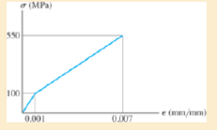
The stress-strain diagram of the material can be approximated by the two line segments. If a bar having a diameter of 80 mm and a length of 1.5 m is made from this material, determine the critical load provided the ends are fixed. Assume that the load acts through the axis of the bar. Use Enqesser’s equation.
Expert Solution & Answer
Want to see the full answer?
Check out a sample textbook solution
Students have asked these similar questions
The stress–strain diagram for a material can be approximated by the two line segments shown. If a bar having a diameter of 80 mm and a length of 1.5 m is made from this material, determine the critical load provided one end is pinned and the other is fixed. Assume that the load acts through the axis of the bar. Use Engesser’s equation.
The stress–strain diagram for a material can be approximated by the two line segments shown. If a bar having a diameter of 80 mm and a length of 1.5 m is made from this material, determine the critical load provided the ends are pinned. Assume that the load acts through the axis of the bar. Use Engesser’s equation.
The stress–strain diagram for a material can be approximated by the two line segments shown. If a bar having a diameter of 80 mm and a length of 1.5 m is made from this material, determine the critical load provided the ends are fixed. Assume that the load acts through the axis of the bar. Use Engesser’s equation.
Chapter 13 Solutions
STANDALONE CODE MECHANICS OF MATERIALS-M
Ch. 13.3 - A 50-in long steel rod has a diameter of 1 in....Ch. 13.3 - A 12-ft wooden rectangular column has the...Ch. 13.3 - The A992 steel column can be considered pinned at...Ch. 13.3 - A steel pipe is fixed supported at its ends. If it...Ch. 13.3 - Determine the maximum force P that can be...Ch. 13.3 - The A992 steel rod BC has a diameter of 50 mm and...Ch. 13.3 - Determine the critical buckling load for the...Ch. 13.3 - The 10-ft wooden rectangular column has the...Ch. 13.3 - The 10-fl wooden column has the dimensions shown....Ch. 13.3 - Determine the maximum force P that can be applied...
Ch. 13.3 - Prob. 34PCh. 13.3 - Prob. 35PCh. 13.3 - The members of the truss are assumed to be pin...Ch. 13.3 - Solve Prob. 1336 for member AB, which has a radius...Ch. 13.3 - Prob. 40PCh. 13.3 - The ideal column has a weight w (force/length) and...Ch. 13.3 - The ideal column is subjected to the force F at...Ch. 13.3 - The column with constant El has the end...Ch. 13.3 - Consider an ideal column as in Fig.13-10 c, having...Ch. 13.3 - Consider an ideal column as in Fig. 13-10d, having...Ch. 13.5 - The aluminium column is fixed at the bottom and...Ch. 13.5 - Prob. 50PCh. 13.5 - Prob. 51PCh. 13.5 - The aluminum rod is fixed at its base and free and...Ch. 13.5 - Assume that the wood column is pin connected at...Ch. 13.5 - Prob. 54PCh. 13.5 - Prob. 59PCh. 13.5 - The wood column is pinned at its base and top. If...Ch. 13.5 - The brass rod is fixed at one end and free at the...Ch. 13.5 - The brass rod is fixed at one end and free at the...Ch. 13.5 - Prob. 65PCh. 13.5 - The W14 53 structural A992 steel column is fixed...Ch. 13.5 - The W14 53 column is fixed at its base and free...Ch. 13.5 - The stress-strain diagram for the material of a...Ch. 13.5 - Construct the buckling curve, P/A versus L/ r, for...Ch. 13.5 - The stress-strain diagram of the material can be...Ch. 13.5 - The stress-strain diagram of the material can be...Ch. 13.6 - Using the AISC equations, select from AppendixB...Ch. 13.6 - Take Y = 50 ksi.Ch. 13.6 - Using the AISC equations, select from AppendixB...Ch. 13.6 - Prob. 83PCh. 13.6 - Using the AISC equations, select from AppendixB...Ch. 13.6 - Prob. 97PCh. 13.6 - Prob. 98PCh. 13.6 - The tube is 0.25 in. thick, is made of 2014-T6...Ch. 13.6 - Prob. 100PCh. 13.6 - A rectangular wooden column has the cross section...Ch. 13.6 - Prob. 102PCh. 13.7 - The W8 15 wide-flange A-36 steel column is...Ch. 13.7 - Prob. 110PCh. 13.7 - A 20-ft-long column is made of aluminum alloy...Ch. 13.7 - A 20-ft-long column is made of aluminum alloy...Ch. 13.7 - The 2014-T6 aluminum hollow column is fixed at its...Ch. 13.7 - The 2014-T6 aluminum hollow column is fixed at its...Ch. 13 - The wood column has a thickness of 4 in. and a...Ch. 13 - The wood column has a thickness of 4 in. and a...Ch. 13 - A steel column has a length of 5 m and is free at...Ch. 13 - The square structural A992 steel tubing has outer...Ch. 13 - If the A-36 steel solid circular rod BD has a...Ch. 13 - If P = 15 kip, determine the required minimum...Ch. 13 - The steel pipe is fixed supported at its ends. If...Ch. 13 - The W200 46 wide-flange A992-steel column can be...Ch. 13 - The wide-flange A992 steel column has the cross...Ch. 13 - The wide-flange A992 steel column has the cross...
Additional Engineering Textbook Solutions
Find more solutions based on key concepts
What is the importance of modeling in engineering? How are the mathematical models for engineering processes pr...
Heat and Mass Transfer: Fundamentals and Applications
What is the weight in newtons of an object that has a mass of (a) 8 kg, (b) 0.04 kg, (c) 760 Mg?
Statics and Mechanics of Materials (5th Edition)
3.3 It is known that a vertical force of 200 lb is required to remove the nail at C from the board. As the nail...
Vector Mechanics for Engineers: Statics
A windowmounted air conditioner removes 3.5kJ from the inside of a home using 1.75 kJ work input. How much ener...
EBK FUNDAMENTALS OF THERMODYNAMICS, ENH
What parts are included in the vehicle chassis?
Automotive Technology: Principles, Diagnosis, And Service (6th Edition) (halderman Automotive Series)
A 20-lb force is applied to the control rod AB as shown. Knowing that the length of the rod is 9 in. and that t...
Statics and Mechanics of Materials
Knowledge Booster


Learn more about
Need a deep-dive on the concept behind this application? Look no further. Learn more about this topic, mechanical-engineering and related others by exploring similar questions and additional content below.Similar questions
- The stress–strain diagram of the material can be approximated by the two line segments. If a bar having a diameter of 80 mm and a length of 1.5 m is made from this material, determine the critical load provided the ends arepinned. Assume that the load acts through the axis of the bar. Use Engesser’s equation.arrow_forwardThe elastic portion of the stress- strain diagram for the 2014-T6 aluminum is shown in the figure. A short cylindrical block, made of this material and has a diameter of 22 mm, is placed in the smooth jaws of a vise, and squeezed until the axial load applied is P= 45 kN. If the material has a Poisson's ratio of = 0.35, determine the new diameter (mm) of the cylindrical block.arrow_forwardA 75 mm diameter compound bar is constructed by shrinking a circularbrass bush onto the outside of a 45 mm diameter solid steel rod. If thecompound bar is then subjected to an axial compressive load of 170 kN,determine the load carried by the steel rod. The modulus of elasticity for steel,Es = 200 GN/m2 , and brass, Eb = 100 GN/m2arrow_forward
- A 75 mm diameter compound bar is constructed by shrinking a circular brass bush onto the outside of a 50 mm diameter solid steel rod. If the compound bar is then subjected to an axial compressive load of 160 kN determine the load carried by the steel rod and the brass bush and the compressive stress set up in each material. For steel, E = 210 GN/m2; for brass, £ = 100 GN/m2arrow_forwardA 25 mm square-cross-section bar of length 300 mm carries an axial compressive load of 50 kN. Determine the stress set up in the bar and its change of length when the load is applied. For the bar material E = 200 MPaarrow_forwardA 100-mm-long rod has a diameter of 15 mm. If an axial tensile load of 100 kN is applied, determine its change in length. Assume linear elastic behavior with E = 200 GPa.arrow_forward
- Please add a Free body diagramarrow_forwardThe pin-connected assembly consists of aluminum rods (1) and (2) and steel rod (3). The aluminum rods each have a diameter of 14 mm and an elastic modulus of E = 70 GPa. The steel rod has a diameter of 15 mm and an elastic modulus of E= 180 GPa. Assume a = 3.0 m, b = 1.6 m, and c = 1.0 m. What is the magnitude of load P that is necessary to displace point A 7mm to the left? A Answer: P = i (3) eTextbook and Media Save for Later B b D kN Attempts: 0 of 5 used Submit Answerarrow_forwardThe pin-connected assembly consists of aluminum rods (1) and (2) and steel rod (3). The aluminum rods each have a diameter of 14 mm and an elastic modulus of E = 70 GPa. The steel rod has a diameter of 15 mm and an elastic modulus of E= 180 GPa. Assume a = 3.0 m, b = 1.6 m, and c = 1.0 m. What is the magnitude of load P that is necessary to displace point A 7 mm to the left? A Answer: P = i (3) eTextbook and Media Save for Later B b D kN Attempts: 0 of 5 used Submit Answerarrow_forward
- The vertical shaft with a diameter of d = 20 mm is supported by a thrust collar that rests on a 21-mm-thick plate. The thrust collar is 16-mm thick. Assume that the load P causes a compressive stress of 190 MPa in the shaft. If the bearing stress between the thrust collar and the plate is limited to 35 MPa, determine the minimum outer diameter Dcollar that must be used for the thrust collar. Thrust collar area Plate Thrust collar d Dcollararrow_forwardIf the allowable tensile stress for the bar is 1st2allow = 21 ksi, and the allowable shear stress for the pin is tallow = 12 ksi, determine the diameter of the pin so that the load P will be a maximum. What is this load? Assumethe hole in the bar has the same diameter d as the pin. Take t = 1 4 in. and w = 2 in.arrow_forwardThe pin-connected assembly consists of aluminum rods (1) and (2) and steel rod (3). The aluminum rods each have a diameter of 14 mm and an elastic modulus of E= 65 GPa. The steel rod has a diameter of 18 mm and an elastic modulus of E= 215 GPa. Assume a = 3.2 m, b = 1.3 m, and c = 1.4 m. What is the magnitude of load P that is necessary to displace point A 10 mm to the left? (1) (3) A 4 Answer: P = i B (2) D KNarrow_forward
arrow_back_ios
SEE MORE QUESTIONS
arrow_forward_ios
Recommended textbooks for you
 Elements Of ElectromagneticsMechanical EngineeringISBN:9780190698614Author:Sadiku, Matthew N. O.Publisher:Oxford University Press
 Mechanics of Materials (10th Edition)Mechanical EngineeringISBN:9780134319650Author:Russell C. HibbelerPublisher:PEARSON
 Thermodynamics: An Engineering ApproachMechanical EngineeringISBN:9781259822674Author:Yunus A. Cengel Dr., Michael A. BolesPublisher:McGraw-Hill Education
 Control Systems EngineeringMechanical EngineeringISBN:9781118170519Author:Norman S. NisePublisher:WILEY
 Mechanics of Materials (MindTap Course List)Mechanical EngineeringISBN:9781337093347Author:Barry J. Goodno, James M. GerePublisher:Cengage Learning
 Engineering Mechanics: StaticsMechanical EngineeringISBN:9781118807330Author:James L. Meriam, L. G. Kraige, J. N. BoltonPublisher:WILEY
Elements Of Electromagnetics
Mechanical Engineering
ISBN:9780190698614
Author:Sadiku, Matthew N. O.
Publisher:Oxford University Press
Mechanics of Materials (10th Edition)
Mechanical Engineering
ISBN:9780134319650
Author:Russell C. Hibbeler
Publisher:PEARSON
Thermodynamics: An Engineering Approach
Mechanical Engineering
ISBN:9781259822674
Author:Yunus A. Cengel Dr., Michael A. Boles
Publisher:McGraw-Hill Education
Control Systems Engineering
Mechanical Engineering
ISBN:9781118170519
Author:Norman S. Nise
Publisher:WILEY
Mechanics of Materials (MindTap Course List)
Mechanical Engineering
ISBN:9781337093347
Author:Barry J. Goodno, James M. Gere
Publisher:Cengage Learning
Engineering Mechanics: Statics
Mechanical Engineering
ISBN:9781118807330
Author:James L. Meriam, L. G. Kraige, J. N. Bolton
Publisher:WILEY
Understanding Failure Theories (Tresca, von Mises etc...); Author: The Efficient Engineer;https://www.youtube.com/watch?v=xkbQnBAOFEg;License: Standard youtube license