Shigley's Mechanical Engineering Design (McGraw-Hill Series in Mechanical Engineering)
10th Edition
ISBN: 9780073398204
Author: Richard G Budynas, Keith J Nisbett
Publisher: McGraw-Hill Education
expand_more
expand_more
Solutions are available for other sections.
Question
error_outline
This textbook solution is under construction.
Students have asked these similar questions
An organic chemist ordered the wrong item. She wanted to obtain 1-hydroxy-2-butanone, butinstead ordered 2-hydroxybutyraldehyde. As a good biochemist, show how the organic chemistcould use biological catalysis to make her desired compound.
Predict the products of aldolase catalyzing the reaction with acetone and (S)-3-hydroxybutyraldehyde.
A cancer patient undergoing chemotherapy is taking a protein kinase inhibitor drug. The patientis an avid marathon runner and does not want to miss his upcoming race. Is it a good idea forthis patient to attempt a marathon while on this medication? Explain why or why not.
Knowledge Booster
Similar questions
- Show the fate of the hydrogen on carbon-2 of glucose.arrow_forwardImagine that aldolase can react with the seven carbon molecule Sedoheptulose-1,7-bisphosphate (below). Use the mechanism to predict the two products generated.arrow_forwardShow the mechanisms of PGK and PFK-1. How are they different?arrow_forward
- Show the fate of the proton on the 4-Oxygen molecule of F-1,6-BP.arrow_forwardSodium borohydride (NaBH4) is a potent inhibitor of aldolase. It is known to ONLY inhibit theenzyme when it is complexed with substrate. Treatment of the enzyme alone has no effect.What is the mechanism for this inhibition?arrow_forwardA non-hydrolysable ATP (AMPPNP - below) is ingested by a graduate student on a dare. Whateffects would you anticipate on his metabolism?arrow_forward
- Show the mechanism for the acid-catalyzed formation of an [α-1,6] glycosidic linkagebetween two molecules of α-D-glucopyranose. Please sketch the structure and use arrows showing electron flow!arrow_forwardI am a Biochemistry student and I am confused on how to analyze FRAP Analysis using Excel Spread Sheets. The following spread sheet has my 0 minute data listed at top and the 4 minute data listed on the bottom. Sheet: https://mnscu-my.sharepoint.com/:x:/g/personal/vi2163ss_go_minnstate_edu/EXjrCizWiXRPmpittqZA12IB8EkB5eE8iaRqj_iun-IAtg?rtime=Wo9zPHFY3Ug The formula for FRAP Analysis is: FRAP value = A (4 min sample) - A (0 min sample) over A (4 min 30 uM ascorbic acid) - A (0 min 30 uM ascorbic acid) multiplied by 30 uM and the dilution factor of 1/10arrow_forwardHO Fill in the missing boxes. ON 800 NO NO Glucose ATP NADH Hexokinase 1,3-Bisphosphoglycerate Mg2+ ADP NAD+, Pi Phosphoglucose Isomerase Glucose-6-Phosphate ON 沁 Glyceraldehyde-3-Phosphate HO حلمة ADP ADP Phospho Mg2+ glycerate Dihydroxyacetone Phosphate ATP kinase ATP Phosphoglycerate 3-phosphoglycerate Mutase H₁₂O Fructose-6-Phosphate ATP Mg2+ ADP Fructose-1,6-Bisphosphate 2-phosphoglycerate H₂O Phosphoenolpyruvate ADP Mg2+ ATP Pyruvatearrow_forward
- In a diffraction experiment of a native crystal, intensity of reflection (-1 0 6) is equivalent to the intensity of reflection (1 0 -6). true or false?arrow_forwardin an x-ray diffraction experiment, moving the detector farther away from the crystal will allow collection of reflection of reflections with high Miller indices. true or false?arrow_forwardShow the mechanism for the acid-catalyzed formation of an [α-1,6] glycosidic linkagebetween two molecules of α-D-glucopyranose.arrow_forward
arrow_back_ios
SEE MORE QUESTIONS
arrow_forward_ios
Recommended textbooks for you
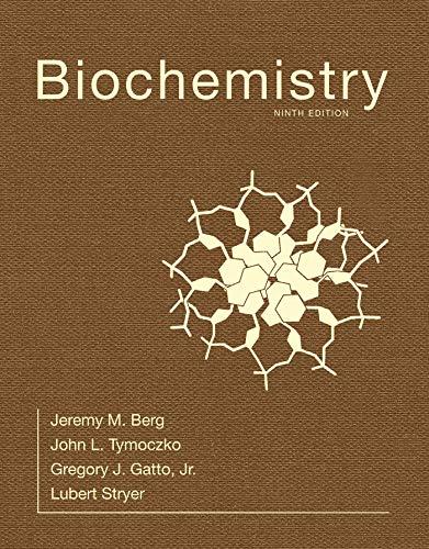
 BiochemistryBiochemistryISBN:9781319114671Author:Lubert Stryer, Jeremy M. Berg, John L. Tymoczko, Gregory J. Gatto Jr.Publisher:W. H. Freeman
 Lehninger Principles of BiochemistryBiochemistryISBN:9781464126116Author:David L. Nelson, Michael M. CoxPublisher:W. H. Freeman
 Fundamentals of Biochemistry: Life at the Molecul...BiochemistryISBN:9781118918401Author:Donald Voet, Judith G. Voet, Charlotte W. PrattPublisher:WILEY
 BiochemistryBiochemistryISBN:9781305961135Author:Mary K. Campbell, Shawn O. Farrell, Owen M. McDougalPublisher:Cengage Learning
 BiochemistryBiochemistryISBN:9781305577206Author:Reginald H. Garrett, Charles M. GrishamPublisher:Cengage Learning
 Fundamentals of General, Organic, and Biological ...BiochemistryISBN:9780134015187Author:John E. McMurry, David S. Ballantine, Carl A. Hoeger, Virginia E. PetersonPublisher:PEARSON

Biochemistry
Biochemistry
ISBN:9781319114671
Author:Lubert Stryer, Jeremy M. Berg, John L. Tymoczko, Gregory J. Gatto Jr.
Publisher:W. H. Freeman

Lehninger Principles of Biochemistry
Biochemistry
ISBN:9781464126116
Author:David L. Nelson, Michael M. Cox
Publisher:W. H. Freeman

Fundamentals of Biochemistry: Life at the Molecul...
Biochemistry
ISBN:9781118918401
Author:Donald Voet, Judith G. Voet, Charlotte W. Pratt
Publisher:WILEY

Biochemistry
Biochemistry
ISBN:9781305961135
Author:Mary K. Campbell, Shawn O. Farrell, Owen M. McDougal
Publisher:Cengage Learning

Biochemistry
Biochemistry
ISBN:9781305577206
Author:Reginald H. Garrett, Charles M. Grisham
Publisher:Cengage Learning

Fundamentals of General, Organic, and Biological ...
Biochemistry
ISBN:9780134015187
Author:John E. McMurry, David S. Ballantine, Carl A. Hoeger, Virginia E. Peterson
Publisher:PEARSON