
Loose Leaf for Engineering Circuit Analysis Format: Loose-leaf
9th Edition
ISBN: 9781259989452
Author: Hayt
Publisher: Mcgraw Hill Publishers
expand_more
expand_more
format_list_bulleted
Concept explainers
Videos
Textbook Question
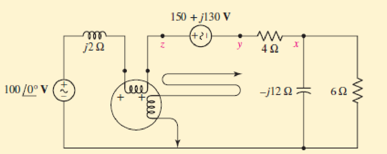
Chapter 12.5, Problem 9P
Determine the wattmeter reading in Fig. 12.24, state whether or not the potential coil had to be reversed in order to obtain an upscale reading, and identify the device or devices absorbing or generating this power. The (+) terminal of the wattmeter is connected to (a) x; (b) y; (c) z.
Expert Solution & Answer
Want to see the full answer?
Check out a sample textbook solution
Students have asked these similar questions
2. Solve the following problem:
A THREE-PHASE PLANT CONSUMES 600 KVA, WITH A VOLTAGE OF 2400 VOLTS AND A POWER FACTOR OF 0.8 BEHIND.
a) DETERMINE THE EQUIVALENT DELTA IMPEDANCE OF THE PLANT.
b) IF THE PLANT WERE A STAR, CALCULATE THE RESISTANCE, REACTANCE AND THE CORRESPONDING PASSIVE ELEMENT.
If a 3- Ø, Y-connected system has a line-to-line voltage of 1103Sin(377t) V, then the line-to-neutral (RMS) voltage would be:
A 3-phase, star-connected alternator supplies a delta connectedload, each phase of which has a resistance of 15Ωand inductive reactance 20Ω. If the line voltage is 400V, calculate (a) the current supplied by the alternator and (b) the output power and kVA ratingof the alternator, neglecting any losses in the line between the alternator and the load.
Chapter 12 Solutions
Loose Leaf for Engineering Circuit Analysis Format: Loose-leaf
Ch. 12.1 - Let and . Find (a) Vad; (b) Vbc; (c) Vcd.Ch. 12.2 - Prob. 2PCh. 12.2 - Modify Fig. 12.9 by adding a 1.5 resistance to...Ch. 12.3 - A balanced three-phase three-wire system has a...Ch. 12.3 - A balanced three-phase three-wire system has a...Ch. 12.3 - Three balanced Y-connected loads are installed on...Ch. 12.4 - Each phase of a balanced three-phase -connected...Ch. 12.4 - Prob. 8PCh. 12.5 - Determine the wattmeter reading in Fig. 12.24,...Ch. 12.5 - Prob. 10P
Ch. 12 - Prob. 1ECh. 12 - Prob. 2ECh. 12 - Prob. 3ECh. 12 - Describe what is meant by a polyphase source,...Ch. 12 - Prob. 5ECh. 12 - Prob. 6ECh. 12 - Prob. 7ECh. 12 - Prob. 8ECh. 12 - Prob. 9ECh. 12 - Prob. 10ECh. 12 - The single-phase three-wire system of Fig. 12.31...Ch. 12 - Prob. 12ECh. 12 - Referring to the balanced load represented in Fig....Ch. 12 - Prob. 14ECh. 12 - Prob. 15ECh. 12 - Consider a simple positive phase sequence,...Ch. 12 - Assume the system shown in Fig. 12.34 is balanced,...Ch. 12 - Repeat Exercise 17 with Rw = 10 , and verify your...Ch. 12 - Prob. 19ECh. 12 - Prob. 20ECh. 12 - Prob. 21ECh. 12 - Prob. 22ECh. 12 - A three-phase system is constructed from a...Ch. 12 - Prob. 24ECh. 12 - Each load in the circuit of Fig. 12.34 is composed...Ch. 12 - Prob. 26ECh. 12 - Prob. 27ECh. 12 - A three-phase load is to be powered by a...Ch. 12 - For the two situations described in Exercise 28,...Ch. 12 - Prob. 30ECh. 12 - Prob. 31ECh. 12 - Prob. 32ECh. 12 - Repeat Exercise 32 if Rw = 1 . Verify your...Ch. 12 - Prob. 34ECh. 12 - Prob. 35ECh. 12 - Prob. 36ECh. 12 - A wattmeter is connected into the circuit of Fig....Ch. 12 - Find the reading of the wattmeter connected in the...Ch. 12 - (a) Find both wattmeter readings in Fig. 12.39 if...Ch. 12 - Circuit values for Fig. 12.40 are , , , , . Find...Ch. 12 - Prob. 41ECh. 12 - Prob. 42ECh. 12 - (a) Is the load represented in Fig. 12.41...Ch. 12 - Prob. 44E
Knowledge Booster


Learn more about
Need a deep-dive on the concept behind this application? Look no further. Learn more about this topic, electrical-engineering and related others by exploring similar questions and additional content below.Similar questions
- A 500-kW 3-phase AC generator rated at 440 V that is displaying 0.83 lag in the power factor meter has a circuit-breaker protected with an over-current relay setting of 125%. What is the actual minimum tripping current of the generator circuit breaker?arrow_forwardA three-phase transmission line delivers 15 MW at 132 kV with 0.8 power factor lagging. The loss in the transmission line is five percentage of the power delivered and the resistance for each transmission line is one ohm/km. (1) The line current ? (2) The length of the transmission line ?arrow_forwardA short 3-phase transmission line connected to a 33kV, 50 Hz generating station at the sending end is required to supply a load of 10 MW at 0·8 lagging power factor at 30 kV at the receiving end. If the minimum transmission efficiency is to be limited to 96%, estimate the per phase value of resistance and inductance of the line. [2·4 Ω; 0·028 H]arrow_forward
- 115 volts 60 cycle source is connected to series CKT, consisting of a fixed resistor and an impedance coil if the resistors and coil voltage drops are 55.4 and 80 volts, respectively under which conditions the current is 1.69 AMP, calculate the resistance and inductance of the impedance coil. solve for power factor solve for L coil Solve for R coilarrow_forward2. A 3Ø, 2000KW, 480V ∆-connected alternator is short-circuited and is operated at ratedspeed to produce rated current at 4A excitation. With the short-circuit remove andwith the excitation adjusted to 5A, the voltage between stator terminal is 330V. Theeffective resistance between terminal as measured with dc is 2Ω. Determine the %V.R.of the alternator at half-load and pf of 0.8 leading without changing any given values.arrow_forwardA sub-station supplies power at 11 kV, 0.8 p.f. lagging to a consumer through a single phase transmission line having total resistance (both go and return) of 0.15 ohm. The voltage drop in the line is 15%. If the same power is to be supplied to the same consumer by two wire d.c. system by a new line having a total resistance of 0.05 ohm and if the allowable voltage drop is 25%. calculate the d.c. supply voltage.arrow_forward
- A three-phase system includes a 346.4 V line-to-line supplying a three-phase motor rated 15KVA 0.8pf lag plus additional balanced constant impedance loads. The single-phase representation of the system is shown below. Assume that sources and loads are Y-connected. 1. What is the RMS value of the line current, I in A? 2. If this set of loads will be supplied through a service transformer. What should the minimum size of the transformer in kVA? 3. What should be the size of three-phase capacitor(that will be added to the load mix) to improve power factor to almost 0.95 lag?arrow_forwardA single – phase transmission line supplies a reactive load at a lagging power factor. The load draws 1.2 pu current at 0.6 pu voltage while drawing 0.5 pu (true) power. If the base voltage is 20 kV and the base current is 160 A, calculate the power factor and the ohmic value of the resistance of the load.arrow_forward. A single-phase 12.47 KV transmission line several kilometers long feeds a load from a substation. The line has a resistance of 2 Ω and a reactance of 20 Ω. Instruments at the substation indicate that the active and reactive power inputs to the line are 4 MW and 3 Mvar, respectively. Calculate a. The line current b. The power factor at the substation c. The active power absorbed by the load d. The reactive power absorbed by the load e. The line voltage at the loadarrow_forward
- A Δ-connected, 60−Hz, balanced, 3ϕ, positive-sequence voltage source is connected to a Δ-connected, symmetric 3ϕ load via a non-ideal transmission line. The line-line voltage magnitude of the source is 480VRMS. The series impedance of each phase of the transmission line is 0.1+j1.5Ω. The impedance of each leg of the load is 3+j6Ω. a. What is the total, 3ϕ complex power consumed by the load. b. What are the total active power losses (all three phases) in the transmission line?arrow_forward115 volts 60 cycle source is connected to series CKT, consisting of a fixed resistor and an impedance coil if the resistors and coil voltage drops are 55.4 and 80 volts, respectively under which conditions the current is 1.69 AMP, calculate the resistance and inductance of the impedance coil.arrow_forwardA 230 V, three phase, 4 wire balance system supplies power to group of lamp of loads. If the line currents are respectively 60 A, 86 A and 40 A respectively, solve for the current in the neutral wires. Assume the power factor of the lamps to be unity.arrow_forward
arrow_back_ios
SEE MORE QUESTIONS
arrow_forward_ios
Recommended textbooks for you
 Introductory Circuit Analysis (13th Edition)Electrical EngineeringISBN:9780133923605Author:Robert L. BoylestadPublisher:PEARSON
 Delmar's Standard Textbook Of ElectricityElectrical EngineeringISBN:9781337900348Author:Stephen L. HermanPublisher:Cengage Learning
 Programmable Logic ControllersElectrical EngineeringISBN:9780073373843Author:Frank D. PetruzellaPublisher:McGraw-Hill Education
 Fundamentals of Electric CircuitsElectrical EngineeringISBN:9780078028229Author:Charles K Alexander, Matthew SadikuPublisher:McGraw-Hill Education
 Electric Circuits. (11th Edition)Electrical EngineeringISBN:9780134746968Author:James W. Nilsson, Susan RiedelPublisher:PEARSON
 Engineering ElectromagneticsElectrical EngineeringISBN:9780078028151Author:Hayt, William H. (william Hart), Jr, BUCK, John A.Publisher:Mcgraw-hill Education,
Introductory Circuit Analysis (13th Edition)
Electrical Engineering
ISBN:9780133923605
Author:Robert L. Boylestad
Publisher:PEARSON
Delmar's Standard Textbook Of Electricity
Electrical Engineering
ISBN:9781337900348
Author:Stephen L. Herman
Publisher:Cengage Learning
Programmable Logic Controllers
Electrical Engineering
ISBN:9780073373843
Author:Frank D. Petruzella
Publisher:McGraw-Hill Education
Fundamentals of Electric Circuits
Electrical Engineering
ISBN:9780078028229
Author:Charles K Alexander, Matthew Sadiku
Publisher:McGraw-Hill Education
Electric Circuits. (11th Edition)
Electrical Engineering
ISBN:9780134746968
Author:James W. Nilsson, Susan Riedel
Publisher:PEARSON
Engineering Electromagnetics
Electrical Engineering
ISBN:9780078028151
Author:Hayt, William H. (william Hart), Jr, BUCK, John A.
Publisher:Mcgraw-hill Education,
How do Electric Transmission Lines Work?; Author: Practical Engineering;https://www.youtube.com/watch?v=qjY31x0m3d8;License: Standard Youtube License