
Loose Leaf for Engineering Circuit Analysis Format: Loose-leaf
9th Edition
ISBN: 9781259989452
Author: Hayt
Publisher: Mcgraw Hill Publishers
expand_more
expand_more
format_list_bulleted
Videos
Textbook Question
Chapter 10.5, Problem 9P
With reference to the network shown in Fig. 10.19, find the input impedance Zin that would be measured between terminals: (a) a and g; (b) b and g; (c) a and b.
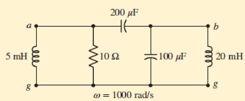
■ FIGURE 10.19
Expert Solution & Answer
Want to see the full answer?
Check out a sample textbook solution
Students have asked these similar questions
For the system given below, Rf=10000 ohm, Ki=0.0125 Nm/A, J=10-6 kg.m2, n=800, Kb=0.0125V/(rad/second), Ra=6.25 ohm, Ks=0.1 A/ rad, with B=0 Nm/(rad/second); Determine the K value for the 9.9% overshoot.Calculate the time of overshoot that will occur for this situation.
The numerical input/output mean optical power ratio in a 1 km, length of optical fiber is found to be 2.5. Calculate the received mean optical power when a mean optical power of 1 mW is launched into a 5 km length of the fiber (assurning no joints or connectors).
Use DFT method to compute the circular convolution of x(n)={4,4} and h(n)={2, 6}.
Chapter 10 Solutions
Loose Leaf for Engineering Circuit Analysis Format: Loose-leaf
Ch. 10.1 - Find the angle by which i1 lags v1 if v1 = 120...Ch. 10.2 - Determine values for A, B, C, and if 40 cos(100t ...Ch. 10.2 - Let vs = 40 cos 8000t V in the circuit of Fig....Ch. 10.3 - Prob. 4PCh. 10.3 - If the use of the passive sign convention is...Ch. 10.4 - Let = 2000 rad/s and t = 1 ms. Find the...Ch. 10.4 - Transform each of the following functions of time...Ch. 10.4 - In the circuit of Fig. 10.17, both sources operate...Ch. 10.5 - With reference to the network shown in Fig. 10.19,...Ch. 10.5 - In the frequency-domain circuit of Fig. 10.21,...
Ch. 10.5 - Determine the admittance (in rectangular form) of...Ch. 10.6 - Use nodal analysis on the circuit of Fig. 10.23 to...Ch. 10.6 - Use mesh analysis on the circuit of Fig. 10.25 to...Ch. 10.7 - If superposition is used on the circuit of Fig....Ch. 10.7 - Prob. 15PCh. 10.7 - Determine the current i through the 4 resistor of...Ch. 10.8 - Select some convenient reference value for IC in...Ch. 10 - Evaluate the following: (a) 5 sin (5t 9) at t =...Ch. 10 - (a) Express each of the following as a single...Ch. 10 - Prob. 3ECh. 10 - Prob. 4ECh. 10 - Prob. 5ECh. 10 - Calculate the first three instants in time (t 0)...Ch. 10 - (a) Determine the first two instants in time (t ...Ch. 10 - The concept of Fourier series is a powerful means...Ch. 10 - Household electrical voltages are typically quoted...Ch. 10 - Prob. 10ECh. 10 - Assuming there are no longer any transients...Ch. 10 - Calculate the power dissipated in the 2 resistor...Ch. 10 - Prob. 13ECh. 10 - Prob. 14ECh. 10 - Prob. 15ECh. 10 - Express the following complex numbers in...Ch. 10 - Prob. 17ECh. 10 - Prob. 18ECh. 10 - Evaluate the following, and express your answer in...Ch. 10 - Perform the indicated operations, and express the...Ch. 10 - Insert an appropriate complex source into the...Ch. 10 - For the circuit of Fig. 10.51, if is = 2 cos 5t A,...Ch. 10 - In the circuit depicted in Fig. 10.51, if is is...Ch. 10 - Employ a suitable complex source to determine the...Ch. 10 - Transform each of the following into phasor form:...Ch. 10 - Prob. 26ECh. 10 - Prob. 27ECh. 10 - The following complex voltages are written in a...Ch. 10 - Assuming an operating frequency of 50 Hz, compute...Ch. 10 - Prob. 30ECh. 10 - Prob. 31ECh. 10 - Prob. 32ECh. 10 - Assuming the passive sign convention and an...Ch. 10 - The circuit of Fig. 10.53 is shown represented in...Ch. 10 - (a) Obtain an expression for the equivalent...Ch. 10 - Determine the equivalent impedance of the...Ch. 10 - (a) Obtain an expression for the equivalent...Ch. 10 - Determine the equivalent admittance of the...Ch. 10 - Prob. 40ECh. 10 - Prob. 41ECh. 10 - Find V in Fig. 10.55 if the box contains (a) 3 in...Ch. 10 - Prob. 43ECh. 10 - Prob. 44ECh. 10 - Design a suitable combination of resistors,...Ch. 10 - Design a suitable combination of resistors,...Ch. 10 - For the circuit depicted in Fig. 10.58, (a) redraw...Ch. 10 - For the circuit illustrated in Fig. 10.59, (a)...Ch. 10 - Referring to the circuit of Fig. 10.59, employ...Ch. 10 - In the phasor-domain circuit represented by Fig....Ch. 10 - With regard to the two-mesh phasor-domain circuit...Ch. 10 - Employ phasor analysis techniques to obtain...Ch. 10 - Determine IB in the circuit of Fig. 10.62 if and ....Ch. 10 - Determine V2 in the circuit of Fig. 10.62 if and ....Ch. 10 - Employ phasor analysis to obtain an expression for...Ch. 10 - Determine the current ix in the circuit of Fig....Ch. 10 - Obtain an expression for each of the four...Ch. 10 - Determine the nodal voltages for the circuit of...Ch. 10 - Prob. 59ECh. 10 - Obtain an expression for each of the four mesh...Ch. 10 - Determine the individual contribution each current...Ch. 10 - Determine V1 and V2 in Fig. 10.68 if I1 = 333 mA...Ch. 10 - Prob. 63ECh. 10 - Obtain the Thvenin equivalent seen by the (2 j) ...Ch. 10 - The (2 j) impedance in the circuit of Fig. 10.69...Ch. 10 - With regard to the circuit depicted in Fig. 10.70,...Ch. 10 - Prob. 67ECh. 10 - Determine the individual contribution of each...Ch. 10 - Determine the power dissipated by the 1 resistor...Ch. 10 - The source Is in the circuit of Fig. 10.75 is...Ch. 10 - Prob. 72ECh. 10 - (a) Calculate values for IL, IR, IC, VL, VR, and...Ch. 10 - In the circuit of Fig. 10.77, (a) find values for...Ch. 10 - The voltage source Vs in Fig. 10.78 is chosen such...Ch. 10 - For the circuit shown in Fig. 10.79, (a) draw the...Ch. 10 - For the circuit shown in Fig. 10.80, (a) draw the...Ch. 10 - (a) Replace the inductor in the circuit of Fig....Ch. 10 - Design a purely passive network (containing only...
Knowledge Booster


Learn more about
Need a deep-dive on the concept behind this application? Look no further. Learn more about this topic, electrical-engineering and related others by exploring similar questions and additional content below.Similar questions
- Which row represent the most stable system and why? nyquist and root locus plot attached.arrow_forwardA 3 phase, 50Hz, Two bus, single transmission line power system consisting of line series resistance of 10, line series inductance of 25 mili Henry and shunt line charging capacitance of 50 micro Farads. Base values are 110kV, 100MVA. Form the bus admittance matrix in per unit.arrow_forwardExplore the challenges and benefits of implementing power electronics-based grid solutions like STATCOM (Static Synchronous Compensator) for voltage control and stability.arrow_forward
- F.) A residential air conditioning unit with an SEER of 14 serves a single-detached family residence in Quezon City, Philippines having an annual cooling load hours of 6,116 hours. The total cooling load is 36,000 Btu/hr. Calculate the approximate annual energy consumption of the A/C unit.arrow_forwardWhat is a Nominal diameter , Power rating, X Max,f/pl(mm),coil (mm),Nominal impedance (O),Sensitivity (dB), Voice coil diameter, Surround Material Cloth - Sealed, Magnet type Ceramic, Magnet assembly flux (T) , Magnet weight (oz), Chassis type Pressed Steel, Cone material Kevlar loaded paper?arrow_forwardQ4 - Calculate the dissipation in power across 20Ω resistor for the FM signal, V(t)= 20 cos(6600 t+ 10 sin 2100 t), if a transmitter radiates a signal of 9.8KW after modulation and 8KW without modulation , Calculate the depth of modulation?arrow_forward
- 1. A boatman rows to a place 48 km distant and back in 14 hours; he finds that he can rous 4 km with the stream in the same time as 3 km against the stream; find the rate of the stream. a. 1 km/hr. b. 3 km/hr c. 2 km/hr d. 4 km/hr 2. The electric power which a transmission line can transmit is proportional to the product of its design voltage and current capacity, and inversely to the transmission distance. A 115 kilovolt line rated at 1000 amperes can transit 150 Megawatts over 150 km. How much power, in Megawatts, can a 230 kilovolt line rated at 1500 amperes transit over 100 km? a. 785 b. 485 c. 675 d. 595arrow_forwardA 50 km communication line has the following parameters: series resistance (R) = 21.4 W/km series inductance (L) = 1.0 mH/km shunt capacitance (C) = 0.062 mF/km shunt conductance (G) = 0.868 mS/km The frequency is 796 Hz and the line is terminated to avoid reflection. If the power at the receiving end is to be –20 dB (6mW reference) and the sending end voltage is 362 V, determine the power at the sending end.arrow_forwardMeasure the diameters of the two wires. Given the density of steel is = 7.8×10³ kg/m3, theoretically estimate fundamental frequencies of the two wires, and calculate the ratio of their frequenciesr unit length? diameters = 0.254mm and 0.432 mmarrow_forward
- f. A residential air conditioning unit with an SEER of 14 serves a single-detached family residence in Quezon City, Philippines having an annual cooling load hours of 6,116 hours. The total cooling load is 36,000 Btu/hr. Calculate the annual operating cost for the A/C unit if the energy cost is Php 7.96/kW-hr.arrow_forwardA (medium) single phase transmission line 100 km long has the following constants : Resistance/km = 0·25 Ω ; Reactance/km = 0·8 Ω Susceptance/km = 14 × 10−6 siemens ; Receiving end line voltage = 66,000 V The line is delivering 15 000 kW at 0 8 power factor lagging. Assuming that the total capacitance of the line is localised at the receiving end alone, determine the sending end current Select one: a. 50 A b. 320 A c. 240 A d. None of The abovearrow_forwardObtain an expression for the power dissipated in the 10 resistor of Fig10.49arrow_forward
arrow_back_ios
SEE MORE QUESTIONS
arrow_forward_ios
Recommended textbooks for you
 Introductory Circuit Analysis (13th Edition)Electrical EngineeringISBN:9780133923605Author:Robert L. BoylestadPublisher:PEARSON
 Delmar's Standard Textbook Of ElectricityElectrical EngineeringISBN:9781337900348Author:Stephen L. HermanPublisher:Cengage Learning
 Programmable Logic ControllersElectrical EngineeringISBN:9780073373843Author:Frank D. PetruzellaPublisher:McGraw-Hill Education
 Fundamentals of Electric CircuitsElectrical EngineeringISBN:9780078028229Author:Charles K Alexander, Matthew SadikuPublisher:McGraw-Hill Education
 Electric Circuits. (11th Edition)Electrical EngineeringISBN:9780134746968Author:James W. Nilsson, Susan RiedelPublisher:PEARSON
 Engineering ElectromagneticsElectrical EngineeringISBN:9780078028151Author:Hayt, William H. (william Hart), Jr, BUCK, John A.Publisher:Mcgraw-hill Education,
Introductory Circuit Analysis (13th Edition)
Electrical Engineering
ISBN:9780133923605
Author:Robert L. Boylestad
Publisher:PEARSON
Delmar's Standard Textbook Of Electricity
Electrical Engineering
ISBN:9781337900348
Author:Stephen L. Herman
Publisher:Cengage Learning
Programmable Logic Controllers
Electrical Engineering
ISBN:9780073373843
Author:Frank D. Petruzella
Publisher:McGraw-Hill Education
Fundamentals of Electric Circuits
Electrical Engineering
ISBN:9780078028229
Author:Charles K Alexander, Matthew Sadiku
Publisher:McGraw-Hill Education
Electric Circuits. (11th Edition)
Electrical Engineering
ISBN:9780134746968
Author:James W. Nilsson, Susan Riedel
Publisher:PEARSON
Engineering Electromagnetics
Electrical Engineering
ISBN:9780078028151
Author:Hayt, William H. (william Hart), Jr, BUCK, John A.
Publisher:Mcgraw-hill Education,
Introduction to Two-Port Networks; Author: ALL ABOUT ELECTRONICS;https://www.youtube.com/watch?v=ru2ItcD6unI;License: Standard Youtube License