
Elements Of Electromagnetics
7th Edition
ISBN: 9780190698614
Author: Sadiku, Matthew N. O.
Publisher: Oxford University Press
expand_more
expand_more
format_list_bulleted
Related questions
Concept explainers
Question
Draw Moment (M) and Shear (V) Diagrams. ( show all work)
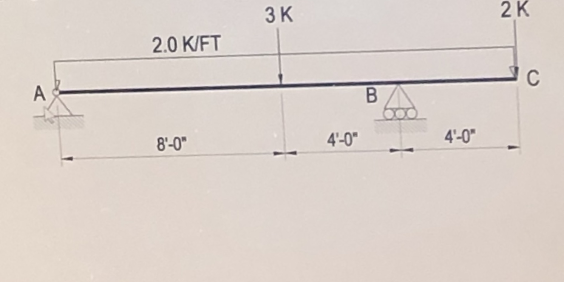

Transcribed Image Text:ЗК
2 K
2.0 K/FT
A
8'-0"
4'-0"
4'-0"
Expert Solution
This question has been solved!
Explore an expertly crafted, step-by-step solution for a thorough understanding of key concepts.

Step by stepSolved in 4 steps with 12 images

Knowledge Booster


Learn more about
Need a deep-dive on the concept behind this application? Look no further. Learn more about this topic, mechanical-engineering and related others by exploring similar questions and additional content below.Similar questions
- 1) Determine the normal force at point E Express your answer to three significant figures and include the appropriate units. 2) Determine the shear force at point E. Express your answer to three significant figures and include the appropriate units. 3) Determine the moment at point E. Express your answer to three significant figures and include the appropriate units.arrow_forwardAnswer the following questions: 1. Describe the difference between Deflecion and Shear force. 2. Describe bending of beam and give example. 3. Describe shear force and bending moment diagram belowarrow_forwardA shear force of S, = 35 kN is applied a distance of a/2 to the left of the vertical mid-line, as shown in the diagram above. The shear modulus of the material G = 35 GPa for all parts. For the main analysis, your tasks are to: a) Find the shear flow distribution around the section b) From this, find the rate of twistarrow_forward
- staticarrow_forwarda) Calculate the reaction forces in terms of F andtheta.b) Calculate the internal shear force and moment as a function of x using cuts and summingforces and moments in terms of F, L, andtheta.c) Calculate the shear force and moments by integration in terms of x, L, F andtheta.d) Assuming a rectangular cross section compute the average normal stress for the case F =10kNat 30° where b =0.04 m, h = 0.08 m, at the point x = L/4, L = 1 m at the centroid.e) With the cross section given above compute the average normal stress for the case F =10kN at30° at the point x = L/4, L = 1 m at each surface of the beam.f) Calculate the shear stress at the top and bottom surface, at the neutral axis and at x = 0.25 mand y = 0.02 m above the neutral axis.arrow_forwardDraw the shear diagram for the beam. Follow the sign convention. (Figure 1) Click on "add vertical line off" to add discontinuity lines. Then click on "add segment" button to add functions between the lines. Note - The curve you choose from the drop-down is only a pictorial representation of a real quadratic/cubic curve. The equation of this curve is not mathematically equivalent to the correct answer. Consequently, slopes at discontinuities and intercepts with the x-axis (if any) are not accurate. ? 4 kip/ft A 12 ft 12 ft No elements selected V (kip) 50 T 40 30 20 10 I (ft) 12 18 24 -10 -20 -30 -40 -50 Add discontinuity lines and select segments to add to the canvas.arrow_forward
- So 873.7 it’s wrong . Determine the maximum value of the bending moment and enter your answer in N-m units.. Remember to also show all your workarrow_forward3. Draw a schematic of the standard convention for the meaning of positive shears and bending moments (see Section 8.2). Use your diagram to help you answer 4 And 5. 4. Determine the internal shear at a section passing through point D. 5. Determine the internal bending moment at a section passing through point. The answers should be according to the answer key- 4. VD = 2000 lb (up) 5. MD = 1556 N-m (clockwise)arrow_forwardFor the following figure, calculate the shear stress, V, when x = 12.0 m. Draw the Shear Force and Bending Moment diagrams. Remember to correctly place the positive or negative sign and highlight the value of the absolute maximum shear force, the maximum positive and negative bending moments.arrow_forward
- Solve it correctly please. I will rate accordinglyarrow_forward1. (a) Draw complete shear force and bending moment diagrams. (b) If x = 0 is at point "A", write equations for the shear force and bending moment, and indicate the appropriate sections. 10 kN 20 kN B k3 m 4 m 3 m D 5 m 15 KN Earrow_forwardHello Sir.Good afternoon. I have a question in my homework related machine element lesson. The following below is my question. Please advice. Thank you so mucharrow_forward
arrow_back_ios
arrow_forward_ios
Recommended textbooks for you
- Elements Of ElectromagneticsMechanical EngineeringISBN:9780190698614Author:Sadiku, Matthew N. O.Publisher:Oxford University Press
 Mechanics of Materials (10th Edition)Mechanical EngineeringISBN:9780134319650Author:Russell C. HibbelerPublisher:PEARSON
 Thermodynamics: An Engineering ApproachMechanical EngineeringISBN:9781259822674Author:Yunus A. Cengel Dr., Michael A. BolesPublisher:McGraw-Hill Education
  Control Systems EngineeringMechanical EngineeringISBN:9781118170519Author:Norman S. NisePublisher:WILEY
 Mechanics of Materials (MindTap Course List)Mechanical EngineeringISBN:9781337093347Author:Barry J. Goodno, James M. GerePublisher:Cengage Learning
 Engineering Mechanics: StaticsMechanical EngineeringISBN:9781118807330Author:James L. Meriam, L. G. Kraige, J. N. BoltonPublisher:WILEY
Elements Of Electromagnetics
Mechanical Engineering
ISBN:9780190698614
Author:Sadiku, Matthew N. O.
Publisher:Oxford University Press
Mechanics of Materials (10th Edition)
Mechanical Engineering
ISBN:9780134319650
Author:Russell C. Hibbeler
Publisher:PEARSON
Thermodynamics: An Engineering Approach
Mechanical Engineering
ISBN:9781259822674
Author:Yunus A. Cengel Dr., Michael A. Boles
Publisher:McGraw-Hill Education
Control Systems Engineering
Mechanical Engineering
ISBN:9781118170519
Author:Norman S. Nise
Publisher:WILEY
Mechanics of Materials (MindTap Course List)
Mechanical Engineering
ISBN:9781337093347
Author:Barry J. Goodno, James M. Gere
Publisher:Cengage Learning
Engineering Mechanics: Statics
Mechanical Engineering
ISBN:9781118807330
Author:James L. Meriam, L. G. Kraige, J. N. Bolton
Publisher:WILEY