Introductory Circuit Analysis (13th Edition)
13th Edition
ISBN: 9780133923605
Author: Robert L. Boylestad
Publisher: PEARSON
expand_more
expand_more
format_list_bulleted
Question
Please answer in typing format

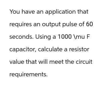
Transcribed Image Text:You have an application that
requires an output pulse of 60
seconds. Using a 1000 \mu F
capacitor, calculate a resistor
value that will meet the circuit
requirements.
Expert Solution
This question has been solved!
Explore an expertly crafted, step-by-step solution for a thorough understanding of key concepts.
Step by stepSolved in 2 steps

Knowledge Booster
Similar questions
- Draw the small signal model of the circuit and derive the equations for vIN and vOUTarrow_forward24. Set up a midpoint bias for a JFET with Ipss = 14 mA and VGs(ofm = -10 V. Use a 24 V dc source as the supply voltage. Show the circuit and resistor values. Indicate the values of Ip, VGs, and Vps-arrow_forwardPlease answer ASAP for like this please It's urgent please I will like it definitely please..arrow_forward
- Please answer ASAP. I will rate Positivelyarrow_forwardVin For the circuit shown, draw the corresponding small signal model. Vcc Vcc Vcc W ww|ll. R1 R2 WWW Q1 Q2 Re Idc Voarrow_forwardUsing LTSpice, simulate the circuit below, use 2N3904 for the transistor. Part ! DC simulation: Measure VCE and Ic. Use .op for the simulation cmd. Remove all capacitors and input signals first. Part 2 AC simulation: Connect all capacitors now and apply an AC signal at the input with an amplitufe of 1mV and a frequency of 1kHz. Determine the Voltage gain of the circuit by dividing Vo with Vin. Show the output for both the DC and AC analysis. Take a screenshot of the circuit and the output voltages and waveforms. Paste in a word file, write your answers, then save as pdf. 50 kΩ Σ 20 0,5 ΚΩ wwwh 9 Vcc=20 V Ca=1 µF = Cc₂ Cg=50 μF 5.6 kn B=100 Ca IST • 3.3 ΚΩ 5 ΚΩΣ CEarrow_forward
- Fill in the table VB VC VE Ic LE I8 fre IT gm 5V Consider the circuit given at the right. 600k 1.5k =0.7, Vauo, B=165) 100uF Vo 1k 100uF a) Perform DC analysis and calculate all VB =? VC:? branch currents, node voltages, and small signal parameters 3K VE=? Rout b) Draw a small-signal equivalent model n Vin Rin 400K c) Calculate Ri, Rout, and Ay=Vou/Vin -5Varrow_forward4) Consider the clamping circuit below, assume Vref=3 V and Vin=5sin(wt) ..Draw the output voltage waveform. Clearly mark the max and min of the voltage.. Vrefarrow_forwardA3 A Thermister has 6500oc resistance at 20oC, and its sensitivity is -7.2%/oC. Design a signalconditioning set-up for an out of 4V, at 21.5oC-with and without self-heating. Let Vs = 10V, and PD=of 4.1mW/oC.arrow_forward
arrow_back_ios
SEE MORE QUESTIONS
arrow_forward_ios
Recommended textbooks for you
 Introductory Circuit Analysis (13th Edition)Electrical EngineeringISBN:9780133923605Author:Robert L. BoylestadPublisher:PEARSON
 Delmar's Standard Textbook Of ElectricityElectrical EngineeringISBN:9781337900348Author:Stephen L. HermanPublisher:Cengage Learning
 Programmable Logic ControllersElectrical EngineeringISBN:9780073373843Author:Frank D. PetruzellaPublisher:McGraw-Hill Education
 Fundamentals of Electric CircuitsElectrical EngineeringISBN:9780078028229Author:Charles K Alexander, Matthew SadikuPublisher:McGraw-Hill Education
 Electric Circuits. (11th Edition)Electrical EngineeringISBN:9780134746968Author:James W. Nilsson, Susan RiedelPublisher:PEARSON
 Engineering ElectromagneticsElectrical EngineeringISBN:9780078028151Author:Hayt, William H. (william Hart), Jr, BUCK, John A.Publisher:Mcgraw-hill Education,

Introductory Circuit Analysis (13th Edition)
Electrical Engineering
ISBN:9780133923605
Author:Robert L. Boylestad
Publisher:PEARSON

Delmar's Standard Textbook Of Electricity
Electrical Engineering
ISBN:9781337900348
Author:Stephen L. Herman
Publisher:Cengage Learning

Programmable Logic Controllers
Electrical Engineering
ISBN:9780073373843
Author:Frank D. Petruzella
Publisher:McGraw-Hill Education

Fundamentals of Electric Circuits
Electrical Engineering
ISBN:9780078028229
Author:Charles K Alexander, Matthew Sadiku
Publisher:McGraw-Hill Education

Electric Circuits. (11th Edition)
Electrical Engineering
ISBN:9780134746968
Author:James W. Nilsson, Susan Riedel
Publisher:PEARSON

Engineering Electromagnetics
Electrical Engineering
ISBN:9780078028151
Author:Hayt, William H. (william Hart), Jr, BUCK, John A.
Publisher:Mcgraw-hill Education,