Concept explainers
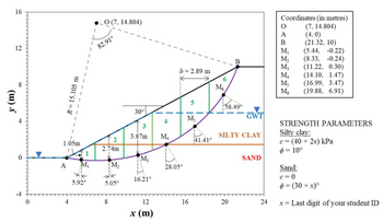
You are required to analyse a slope stability problem using the Swedish method for failure along the slip surface as shown in the figure below. The slope is inclined at an angle of 30° to the horizontal and has a height of 10 m. The ground water table (GWT) is located at a depth of 5.1 m below the crest. It goes along the slope and reaches at the toe level as shown in the figure.
Soil investigation revealed that the site consists of a layer of silty clay overlying a layer of sand. Assume c = (40 + 2x) kPa and ϕ = 10° for the silty clay, and c = 0 and ϕ = (30 + x)° for the sand layer; where x is the last digit of your student ID (e.g., if your student ID is 5746189, x = 9). All slices have equal width (b = 2.89 m) and the slices are numbered 1‒6 from left to right. The coordinates of the midpoint of the bases (M , M , M , M , M , M ) of the slices are shown on the right side of the figure. The weights of slices 1‒6 are as follows (in kN/m): W1 = 53.5, W2 = 141.3, W3 = 199.6, W4= 224.8, W5= 206.3, W6 = 108.2. Assume γ = 10 kN/m3 .
a) Calculate the average cohesion (c1 , c 2, c3 , c 4, c5 , c6 ) and friction angle (ϕ 1, ϕ2 , ϕ 3, ϕ4 , ϕ5 , ϕ 6) for the 6 slices.
b) Calculate the pore pressures acting at the bases of the slices: u1 , u2, u3 , u4, u5 , u6 .
c) Calculate the resisting moment and the disturbing moment.
(d) Estimate the factor of safety and comment on the stability of the slope.
Note: Make approximations wherever necessary. Mention proper units in your calculations.

Step by stepSolved in 4 steps with 11 images

- A cut slope was excavated in sand. The slope is shown in following attachment . To find the properties of the sand, representative samples were taken for the soil and tested in atriaxial apparatus. A consolidated drained triaxial test was conducted. The result is given below:Chamber pressure = 103 kN/m2Deviator stress at failure = 234.6 kN/m2We know the unit weight of the sand is 16 kN/m3.Use the ordinary method of slices (use 7 slices) and estimate the factor of safety against sliding forshown slip surface and comment on the calculated factor of safety.Please note that:1. The figure is not in scale. You may resketch it in scale and calculate the factor of safety2. The slip surface is circular and passes through the toe of the embankmentarrow_forwardThe figure below shows a proposed site where an excavation will be made. The 12 ft layer of sand will be removed, so that the top of the 30 ft normally consolidated clay layer will be exposed (Assume that changes in GWT do not affect γt of clay). a. Assume that the water-table location remains the same during excavation. Compute the σ, σ′v, and u values at the middle of the clay layer before and after the excavation b. Assuming 1-D conditions, compute how much the clay layer will deform due to this excavation, in inches. Specify whether this is settlement or heavearrow_forwardA cut is made into a homogeneous soil as depicted in the figure below, at an angle of 60° with the horizontal. Calculate the resisting shear force in kN along the failure plane given that the shear force applied by the overlying soil wedge is 120 kN. The failure plane is at an angle of 40° from the horizontal direction and the ground water level is below this plane. Assume drained conditions for this question.arrow_forward
- 7. Refer to soil profile shown in Fig. 1. If the cone penetration resistance (qc) at ʻA’ as determined by an electric friction cone penetrometer is 0.6 MN/m², determine the undrained cohesion, cu and OCR. 2 m Clay, y= 18.3 kN/m³ 6 m Clay, Ysat 19 kN/m • Aarrow_forwardA 10 m high sope of dry clay sol (unil weight = 20 N/m) with a slope angle of 45 and the circular slip suriace, is shown in the figure (not drawn to the scale). The weight of the slp wedge is denoted by W. The undrained unt cohosion (C) is 60 kPa. 10m Unit weight= 20 kN m C = 60 kPa 10m 448m, 45% The facter of safety of the slooe against sip failure. ISarrow_forwardA cohesionless sand is tested in a direct shear apparatus with a squareshear box 6.00 cm in size. Normal load at failure was 93.8 N with a maximum shear loadof 38.7 N. Find friction angle (φ) and shear strength (τ).arrow_forward

 Structural Analysis (10th Edition)Civil EngineeringISBN:9780134610672Author:Russell C. HibbelerPublisher:PEARSON
 Principles of Foundation Engineering (MindTap Cou...Civil EngineeringISBN:9781337705028Author:Braja M. Das, Nagaratnam SivakuganPublisher:Cengage Learning
 Fundamentals of Structural AnalysisCivil EngineeringISBN:9780073398006Author:Kenneth M. Leet Emeritus, Chia-Ming Uang, Joel LanningPublisher:McGraw-Hill Education
 Traffic and Highway EngineeringCivil EngineeringISBN:9781305156241Author:Garber, Nicholas J.Publisher:Cengage Learning


