Database System Concepts
7th Edition
ISBN: 9780078022159
Author: Abraham Silberschatz Professor, Henry F. Korth, S. Sudarshan
Publisher: McGraw-Hill Education
expand_more
expand_more
format_list_bulleted
Question
sensors.io code:
lass Sensor {
public:
virtual float read() = 0;
virtual const char* sensorName();
protected:
Sensor(int p) : pin(p) {}
protected:
int pin;
};
class Thermistor : public Sensor {
public:
Thermistor(int);
const char* sensorName();
float read();
};
class LightSensor : public Sensor {
public:
LightSensor(int);
const char* sensorName();
float read();
};
// TODO write the Thermistor and LightSensor constructor, sensorName,
// and read methods
Sensor* sensors[2];
void setup() {
Serial.begin(9600);
sensors[0] = new Thermistor(A3);
sensors[1] = new LightSensor(A0);
}
int sensorno = 0;
void loop() {
// TODO write code to check if data is available from the serial port.
// If the user types in a '0', change the sensorno to 0.
// If the user types in a '1', change the sensorno to 1.
Sensor* mysensor = sensors[sensorno];
Serial.print(mysensor->sensorName());
Serial.print(": ");
Serial.println(mysensor->read());
delay(1000);
}

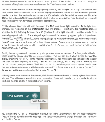
Transcribed Image Text:name of the sensor - in the case of the Thermistor, you should return the "Thermistor" string and
in the case of Light Sensor, you should return the "Light Sensor" string.
The read method should read the analog signal specified by pin using the analogRead function and
then convert that ADC value to a float value appropriate for that sensor. For the thermistor, you can
use the code from the previous labs to convert the ADC value into the Fahrenheit temperature. Since the
ADC on the Arduino is 10-bit instead of 8-bit, which is what we were getting over the serial port, you will
need to adjust the ADC to voltage calculations appropriately.
For the photoresistor, you will need to convert the ADC value into a light intensity. As the light level
changes, the resistance of the photoresistor (Rp) will change - specifically, the resistance changes
according to the following formula: R₂ = R₁ where L is the light intensity. In other words, RP is
inversely proportional to L. The analog voltage that you will be measuring is given by the voltage divider
formula Vana-R+1Kn
where Vana is the analog voltage. As with the thermistor, you will need to convert
the ADC value that you get from analogRead into a voltage. Once you get the voltage, you can use the
above formulas to calculate L which is what your Light Sensor::read method should return.
Assume that RoLo = 20000.
5V-1KN
Finally, the setup code will create an array with pointers to the two sensors. The loop code will select
which sensor to display using the sensorno variable. The user can select which sensor they want to
display by sending '0' or '1' in the Arduino serial monitor. You will need to add some code to check if
the user has sent anything by calling Serial.available (), and if any data is available, call
Serial.read() to get the data. Check if it is '0' or '1', and change sensorno appropriately. Note
that the Arduino serial monitor will also send a newline ('\n') character in addition to the '0' or '1'.
So, you can just ignore any character that is not a '0' or '1'
To bring up the serial monitor in the Arduino, click the serial monitor button at the top right of the Arduino
window. This will open a new tab in the output window. You should see the output from the Arduino in
the Serial monitor tab and it will update every second.
Serial Monitor
Serial Monitor
You can send the '0' or '1' message in the input field in the Serial monitor. You will need to press the
"Return" key to actually send the message. The sensor output should change between the Thermistor
and the Light Sensor

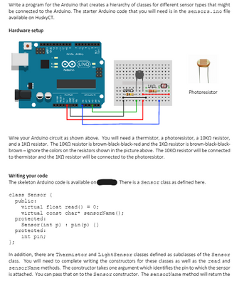
Transcribed Image Text:Write a program for the Arduino that creates a hierarchy of classes for different sensor types that might
be connected to the Arduino. The starter Arduino code that you will need is in the sensors.ino file
available on HuskyCT.
Hardware setup
NATA PVM-)
O UNO
Arduino
ANALUSIN
252234
888
• ΙΚΩ,
Photoresistor
Wire your Arduino circuit as shown above. You will need a thermistor, a photoresistor, a 10K resistor,
and a 1KQ resistor. The 10K resistor is brown-black-black-red and the 1KQ resistor is brown-black-black-
brown-ignore the colors on the resistors shown in the picture above. The 10K resistor will be connected
to thermistor and the 1KQ resistor will be connected to the photoresistor.
Writing your code
The skeleton Arduino code is available on
class Sensor {
};
public:
virtual float read() = 0;
There is a Sensor class as defined here.
virtual const char* sensorName();
protected:
Sensor (int p)
protected:
int pin;
pin (p) {})
In addition, there are Thermistor and Light Sensor classes defined as subclasses of the Sensor
class. You will need to complete writing the constructors for these classes as well as the read and
sensorName methods. The constructor takes one argument which identifies the pin to which the sensor
is attached. You can pass that on to the Sensor constructor. The sensorName method will return the
Expert Solution
This question has been solved!
Explore an expertly crafted, step-by-step solution for a thorough understanding of key concepts.
This is a popular solution
Trending nowThis is a popular solution!
Step by stepSolved in 2 steps

Knowledge Booster
Similar questions
- Refer again to the UML Class Description for Student. Write the code for the class_text method using a dictionary structure to assign the appropriate text value for the class_code value.arrow_forwardDescribe how classes are implemented.arrow_forwardclass box { int width; int height; int length; int volume; void volume(int height, int length, int width) { volume = width*height*length; } } class Prameterized_method { public static void main(String args[]) { box obj = new box(); obj.height = 1; obj.length = 5; obj.width = 5; obj.volume(3,2,1); System.out.println(obj.volume); } } Give result for the code Java Try to do ASAParrow_forward
- C# List the differences between CommissionEmployee class and BasePlusCommissionEmployee class public class BasePlusCommissionEmployee { public string FirstName { get; } public string LastName { get; } public string SocialSecurityNumber { get; } private decimal grossSales; private decimal commissionRate; private decimal baseSalary; public BasePlusCommissionEmployee(string firstName, string lastName, string socialSecurityNumber, decimal grossSales, decimal commissionRate, decimal baseSalary) { FirstName = firstName; LastName = lastName; SocialSecurityNumber = socialSecurityNumber; GrossSales = grossSales; CommissionRate = commissionRate; BaseSalary = baseSalary; } public decimal GrossSales { get { return grossSales; } set { if (value < 0) // validation { throw new ArgumentOutOfRangeException(nameof(value),…arrow_forwardclass FoodItem: # TODO: Define constructor with parameters to initialize instance # attributes (name, fat, carbs, protein) def get_calories(self, num_servings): # Calorie formula calories = ((self.fat * 9) + (self.carbs * 4) + (self.protein * 4)) * num_servings; return calories def print_info(self): print('Nutritional information per serving of {}:'.format(self.name)) print(' Fat: {:.2f} g'.format(self.fat)) print(' Carbohydrates: {:.2f} g'.format(self.carbs)) print(' Protein: {:.2f} g'.format(self.protein)) if __name__ == "__main__": food_item1 = FoodItem() item_name = input() amount_fat = float(input()) amount_carbs = float(input()) amount_protein = float(input()) food_item2 = FoodItem(item_name, amount_fat, amount_carbs, amount_protein) num_servings = float(input()) food_item1.print_info() print('Number of calories for {:.2f} serving(s):…arrow_forwardpublic class Plant { protected String plantName; protected String plantCost; public void setPlantName(String userPlantName) { plantName = userPlantName; } public String getPlantName() { return plantName; } public void setPlantCost(String userPlantCost) { plantCost = userPlantCost; } public String getPlantCost() { return plantCost; } public void printInfo() { System.out.println(" Plant name: " + plantName); System.out.println(" Cost: " + plantCost); }} public class Flower extends Plant { private boolean isAnnual; private String colorOfFlowers; public void setPlantType(boolean userIsAnnual) { isAnnual = userIsAnnual; } public boolean getPlantType(){ return isAnnual; } public void setColorOfFlowers(String userColorOfFlowers) { colorOfFlowers = userColorOfFlowers; } public String getColorOfFlowers(){ return colorOfFlowers; } @Override public void printInfo(){…arrow_forward
- UML for the following Code: public class ProductOrder { private int numBook = 0; private int numCD = 0; private int numDVD = 0; public ProductOrder(int numBook, int numCD, int numDVD){ this.numBook = numBook; this.numCD = numCD; this.numDVD = numDVD; } public int getBook(){ return numBook; } public void setBook(int numBook){ this.numBook = numBook; } public int getCD(){ return numCD; } public void setCD(int numCD){ this.numCD = numCD; } public int getDVD(){ return numDVD; } public void setDVD(int numDVD){ this.numDVD = numDVD; } public int getProductTotal(){ return getBook() + getCD() + getDVD(); } }arrow_forwardpublic class Course { private String courseNumber, courseTitle; public Course() { } public Course(String courseNumber, String courseTitle) { this.courseNumber = courseNumber; this.courseTitle = courseTitle; } public void setCourseNumber(String courseNumber) { this.courseNumber = courseNumber; } public void setCourseTitle(String courseTitle) { this.courseTitle = courseTitle; } public String getCourseNumber() { return courseNumber; } public String getCourseTitle() { return courseTitle; } public void printInfo() { System.out.println("Course Information: "); System.out.println(" Course Number: " + courseNumber); System.out.println(" Course Title: " +…arrow_forwardQuestion 13 What is outpout? public class Vehicle { public void drive(){ System.out.println("Driving vehicle"); } } public class Plane extends Vehicle { @Override public void drive(){ System.out.println("Flying plane"); } public static void main(String args[]) { Vehicle myVehicle= = new Plane(); myVehicle.drive(); } Driving vehicle syntax error Flying plane Driving vehicle Flying plane }arrow_forward
- pythonarrow_forwardDesign a class which provides a lock only if there are no possible deadlocksarrow_forwardclass smart { public: void print() const; void set(int, int); int sum(); smart(); smart(int, int); private: int x; int y; int secret(); }; class superSmart: public smart { public: void print() const; void set(int, int, int); int manipulate(); superSmart(); superSmart(int, int, int); private: int z; }; Now answer the following questions: a. Which private members, if any, of smart are public members of superSmart? b. Which members, functions, and/or data of the class smart are directly accessible in class superSmart?arrow_forward
arrow_back_ios
SEE MORE QUESTIONS
arrow_forward_ios
Recommended textbooks for you
 Database System ConceptsComputer ScienceISBN:9780078022159Author:Abraham Silberschatz Professor, Henry F. Korth, S. SudarshanPublisher:McGraw-Hill Education
 Starting Out with Python (4th Edition)Computer ScienceISBN:9780134444321Author:Tony GaddisPublisher:PEARSON
 Digital Fundamentals (11th Edition)Computer ScienceISBN:9780132737968Author:Thomas L. FloydPublisher:PEARSON
 C How to Program (8th Edition)Computer ScienceISBN:9780133976892Author:Paul J. Deitel, Harvey DeitelPublisher:PEARSON
 Database Systems: Design, Implementation, & Manag...Computer ScienceISBN:9781337627900Author:Carlos Coronel, Steven MorrisPublisher:Cengage Learning
 Programmable Logic ControllersComputer ScienceISBN:9780073373843Author:Frank D. PetruzellaPublisher:McGraw-Hill Education

Database System Concepts
Computer Science
ISBN:9780078022159
Author:Abraham Silberschatz Professor, Henry F. Korth, S. Sudarshan
Publisher:McGraw-Hill Education

Starting Out with Python (4th Edition)
Computer Science
ISBN:9780134444321
Author:Tony Gaddis
Publisher:PEARSON

Digital Fundamentals (11th Edition)
Computer Science
ISBN:9780132737968
Author:Thomas L. Floyd
Publisher:PEARSON

C How to Program (8th Edition)
Computer Science
ISBN:9780133976892
Author:Paul J. Deitel, Harvey Deitel
Publisher:PEARSON

Database Systems: Design, Implementation, & Manag...
Computer Science
ISBN:9781337627900
Author:Carlos Coronel, Steven Morris
Publisher:Cengage Learning

Programmable Logic Controllers
Computer Science
ISBN:9780073373843
Author:Frank D. Petruzella
Publisher:McGraw-Hill Education